Watlow F4T Install & Troubleshooting • 10 • Chapter 2 Install and Wire
5. With the component side of the module facing right (viewing the controller from the
rear) insert the module in to the slot until it latches.
6. Remove the screw terminal block from the module.
7. Wire eld devices to the appropriate terminals (see. Wiring details for each input and
output are provided in the following sections.
8. Reconnect the wired screw terminal block to the module. Be sure to reconnect the ter-
minal block to the correct module.
9. Restore power to the controller.
Note:
If a module is swapped out and replaced with a different type or moved to another open
slot after configuration, the controller will no longer function properly without being re-
configured using Composer™ software.
Note:
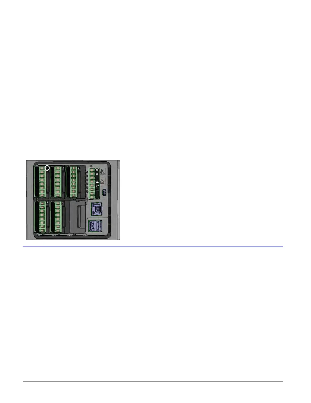
To minimize the possibility of unwanted downtime due to a module being removed and
installed into the wrong slot, affix the slot number labels (as directed in step 4 above) to
each module (as shown in the graphic below, white circle) and each removable screw ter-
minal block.
Wiring the Modules
Prior to wiring any of the I/O modules described in this document it is recommended that
the warnings and notes listed below be reviewed.
CAUTION:
ç
To prevent damage to the controller, do not connect wires to unused terminals.
AVERTISSEMENT: Pour prévenir tout endommagement du régulateur, ne pas faire de raccor-
dements à des bornes inutilisées.
CAUTION
ç
Quencharc Note:
Switching pilot duty inductive loads (relay coils, solenoids, etc.) with the mechanical relay,
solid-state relay or open collector output options requires the use of an R.C. suppressor for
AC load or a diode for a DC load.
AVERTISSEMENT: les charges inductives de commutation de lampes témoins (bobines de re-
lais, solénoïdes, etc.) avec des options de sortie à relais mécanique, de relais statique ou col-
lecteur ouvert requièrent un dispositif antiparasite R.C.
Anderson-Bolds ~ 216-360-9800

 Loading...


