Watlow F4T Install & Troubleshooting • 48 • Chapter 6 Appendix
Universal Process/Retransmit Output
• Universal process/retransmit, Output range selectable:
- 0 to 10V Î(dc) into a min. 1,000Ω load
- 0 to 20mA into max. 800Ω load
Resolution
- dc ranges: 2.5mV nominal resolution
- mA ranges: 5 µA nominal resolution
Calibration Accuracy
- dc ranges: ±15 mV
- mA ranges: ±30 µA
Temperature Stability
- 100 ppm/°C
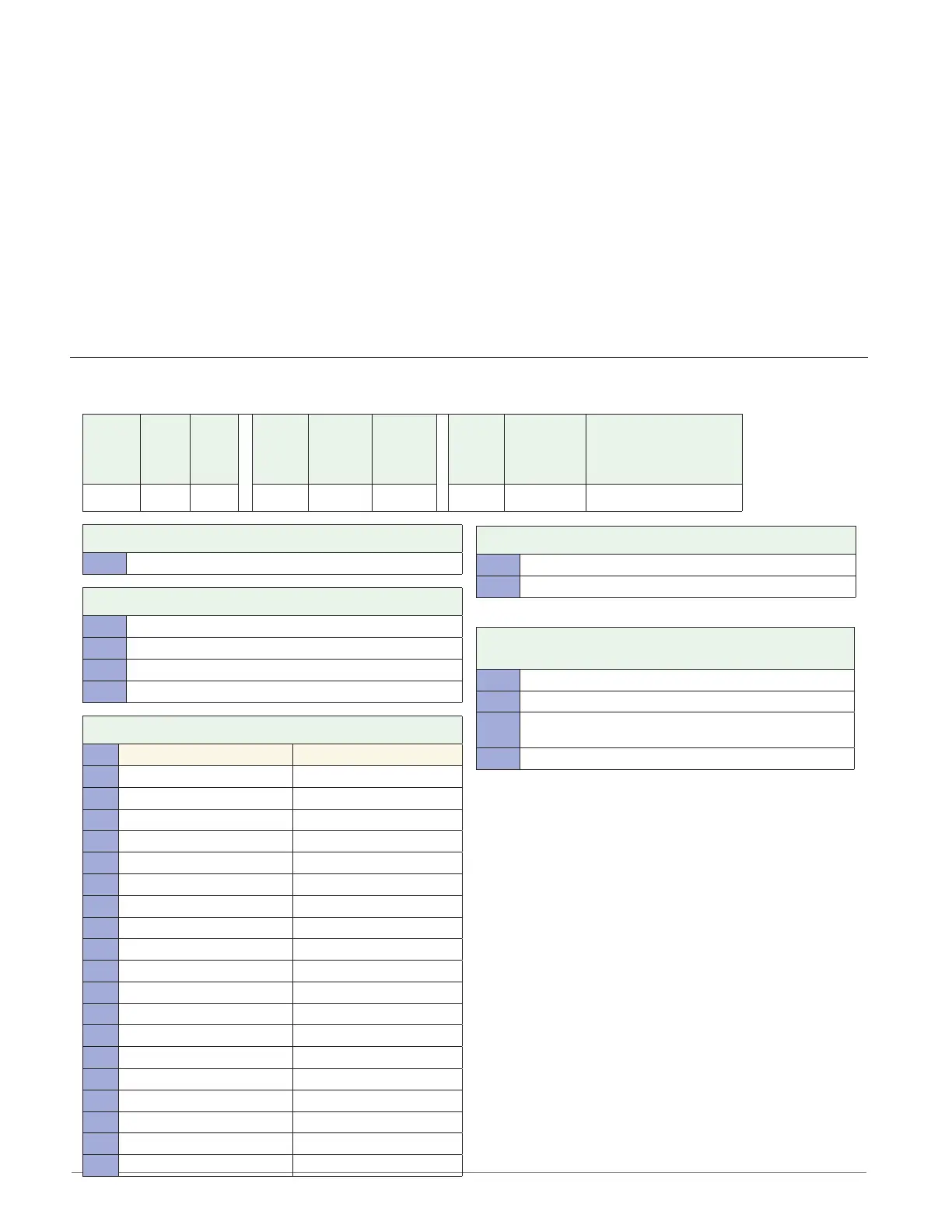
Flex Module - Mixed I/O Ordering Information
Part Number
① ② ③
Module
ID Type
④
Future
Option
-
⑤
Input
Hardware
⑥ ⑦
Output
Hardware
Options
⑧
Future
Option
-
⑨
Future
Options
⑩
Custom
Options and
Connectors
⑪ d
Custom Options - Firmware,
Overlay, Preset Parameters,
Locked Code
FM M A A A
③ Module Type
M = Mixed I/0
⑤ Input Hardware
A = None
U = Universal input - T/C, RTD 2- or 3-wire, 0-10VDC, 0-20mA
T = Thermistor input
C = Current transformer input
⑥ ⑦ Output Hardware Options
Output 1 Output 2
AA = None None
AJ = None Mechanical relay 5A, Form A
AK = None SSR Form A, 0.5A
CA = Switched dc/open collector None
CH = Switched dc/open collector NO-ARC 12A power control
CC = Switched dc/open collector Switched dc
CJ = Switched dc/open collector Mechanical relay 5A, Form A
CK = Switched dc/open collector SSR Form A, 0.5A
EA = Mechanical relay 5A, Form C None
EH = Mechanical relay 5A, Form C NO-ARC 12A power control
EC = Mechanical relay 5A, Form C Switched dc
EJ = Mechanical relay 5A, Form C Mechanical relay 5A, Form A
EK = Mechanical relay 5A, Form C SSR Form A, 0.5A
FA = Universal process/retransmit None
FC = Universal process/retransmit Switched dc
FJ = Universal process/retransmit Mechanical relay 5A, Form A
FK = Universal process/retransmit SSR Form A, 0.5A
KH = SSR Form A, 0.5A NO-ARC 12A power control
KK = SSR Form A, 0.5A SR Form A, 0.5A
⑩ Custom Options and Connectors
A = Right angle screw connector (standard)
F = Front screw connector
⑪ d Custom Options - Firmware, Overlay,
Preset Parameters, Locked Code
AA = Standard with quick start guide
AB = Standard without quick start guide
AC = Replacement connectors hardware only - for the entered
model number
XX = Custom
Anderson-Bolds ~ 216-360-9800

 Loading...


