Watlow F4T Install & Troubleshooting • 4 • Chapter 2 Install and Wire
Chapter 2: Install and Wire
2
Getting Started Quickly...The Logical Approach
The steps below outline installation and wiring for the base alone. More detail for each is
provided in the following sections.
1. Using this document for orientation, nd the base part number and note any installed
options as well as input voltage requirements.
2. Mount/install the base in the panel (see instructions below for panel mount or ush
mount options).
3. Ensure that incoming power is off and connect to the base power supply connector (see
section "Wiring the F4T Base").
4. Make note of any I/O module slot dependencies installing each one into an appropriate
base slot (see graphic entitled F4T Slot Dependencies under "Flex Module Installation").
5. Connect the wires from each eld device to the associated I/O module connector (see
section "Wiring the Modules").
6. Insert all wired I/O connectors onto the applicable modules and apply power to the
base.
7. Connect the controller to a computer running Composer™ software using an Ethernet
cable (see section "Connecting the F4T Base to a PC").
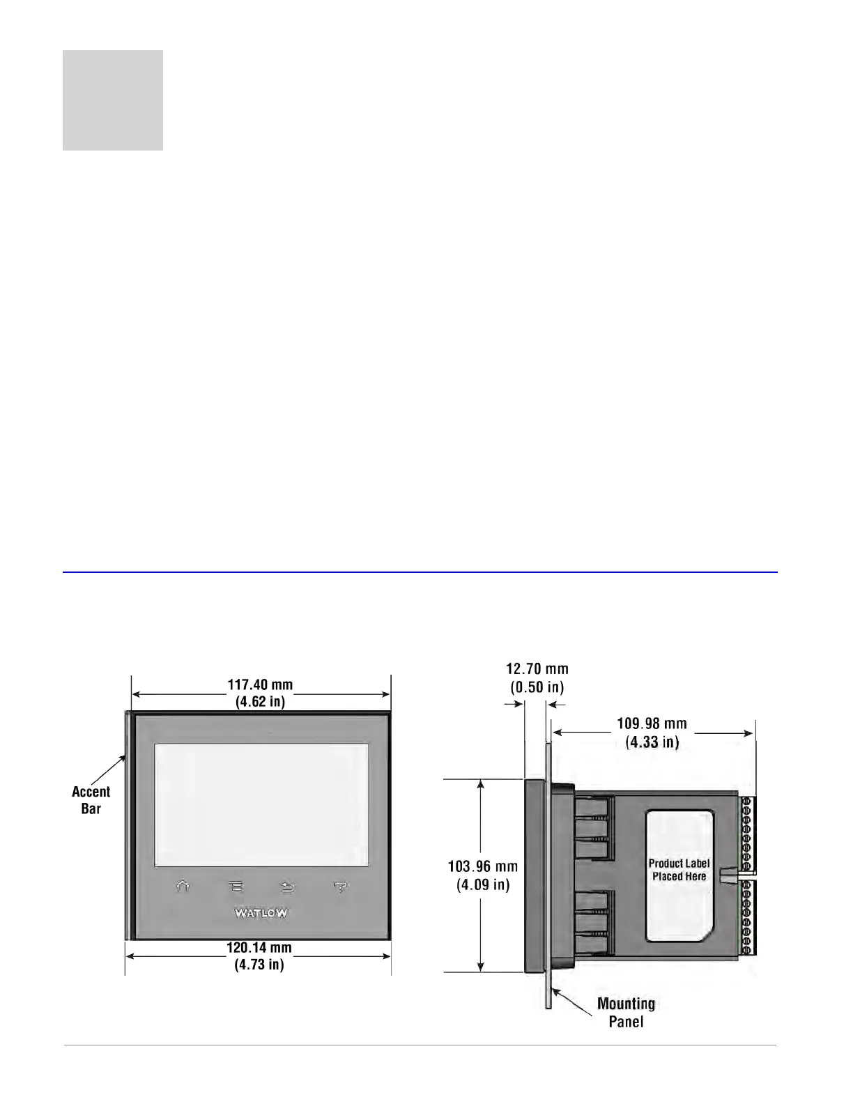
Dimensions
Panel Mount
Front View Side View
Anderson-Bolds ~ 216-360-9800

 Loading...


