Watlow F4T Install & Troubleshooting • 30 • Chapter 4 Calibration
Chapter 4: Calibration
4
Calibrating the F4T Inputs
All controllers are calibrated and are accurate to the specied specications (see Appendix
for specications) when they ship from the manufacturing facility.
If an input is suspect as being out of calibration it is recommended that prior to perform-
ing any calibration procedure that the user verify that the displayed readings are not within
published specications. Input a known value from a precision source to the analog input and
subtract the displayed value with the known value and compare this difference to the pub-
lished accuracy range specication (see Appendix for specications) for that type of input.
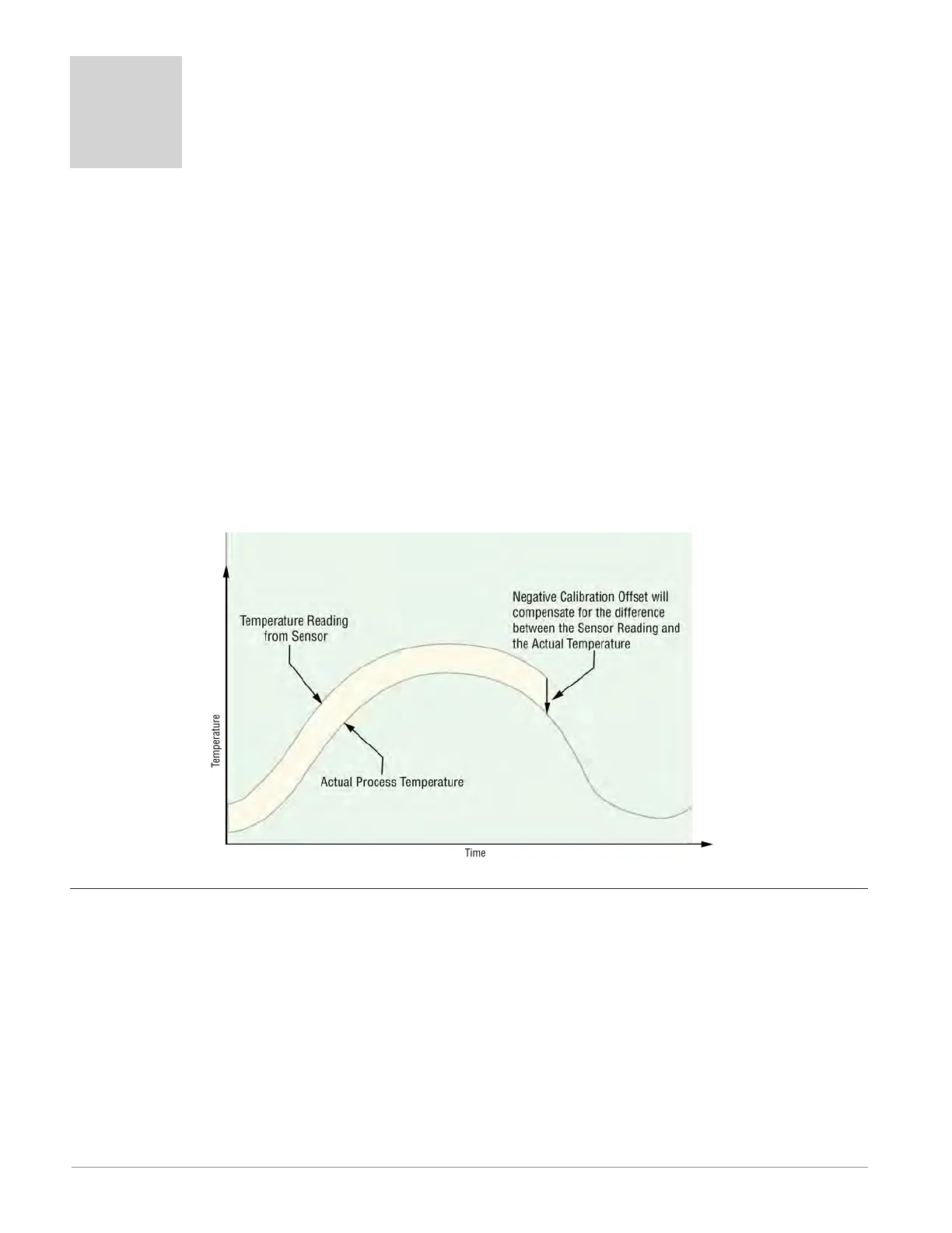
Use of the Calibration Offset parameter found when viewing the Universal Input parameters
from within Composer™ software or while viewing the input from the front panel Operations
menu, shifts the readings across the entire displayed range by the offset value. Use this pa-
rameter to compensate for sensor error or sensor placement error. Typically this value is set
to zero.
Required Equipment When Performing Calibration
Obtain a precision source for millivolts, volts, milliamperes or resistance depending on the
sensor type to be calibrated. Use copper wire only to connect the precision source to the
controller’s input. Keep leads between the precision source and controller as short as possi-
ble to minimize error. In addition, a precision volt/ohm meter capable of reading values to 4
decimal places or better is recommended. Prior to calibration, connect this volt/ohm meter
to the precision source to verify accuracy.
Actual input values do NOT have to be exactly the recommended values, but it is critical
that the actual value of the signal connected to the controller be accurately known to at
least four digits.
Anderson-Bolds ~ 216-360-9800

 Loading...


