Watlow F4T Install & Troubleshooting • 49 • Chapter 6 Appendix
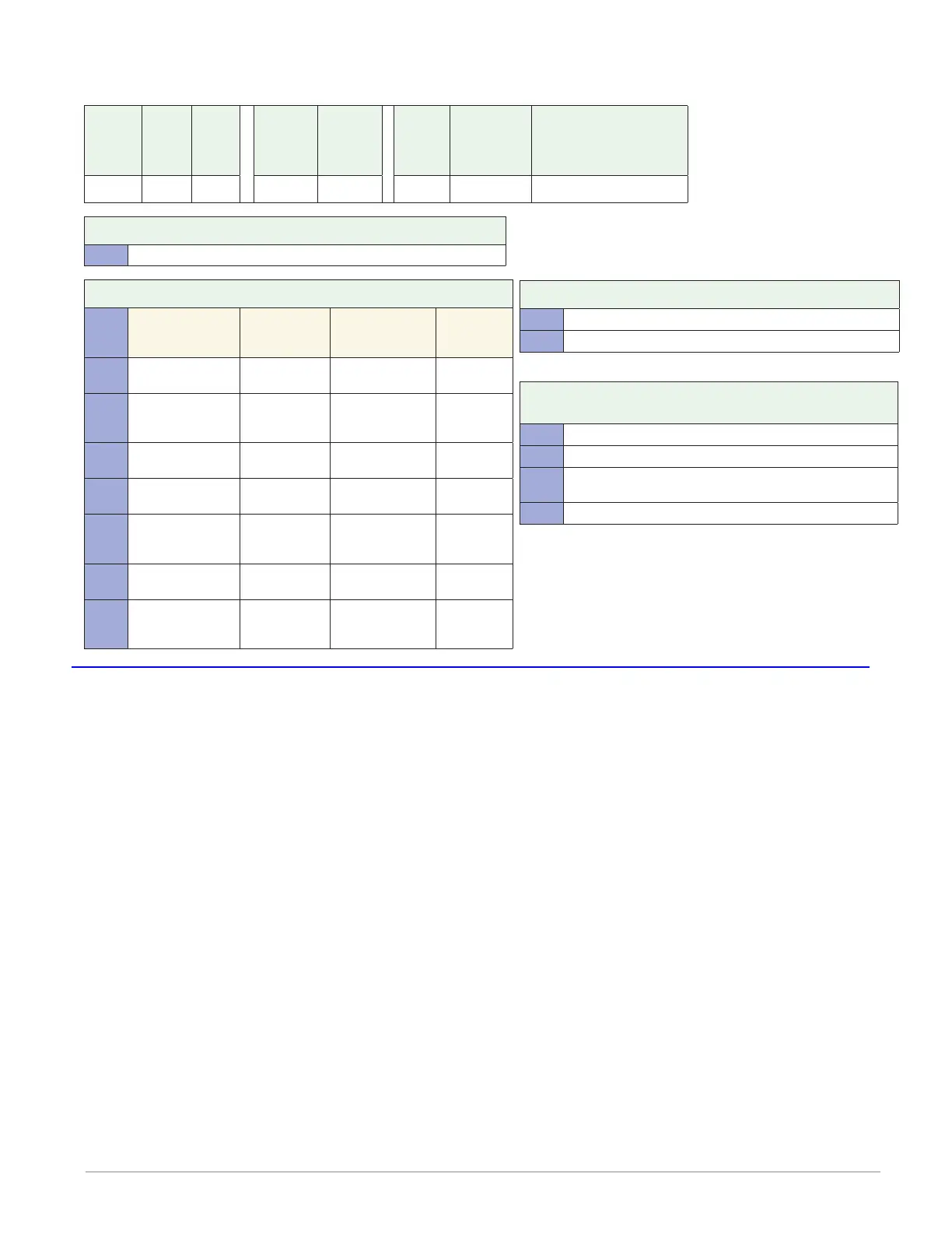
Flex Module - Limit Ordering Information
Part Number
① ② ③
Module
ID Type
④
Future
Option
-
⑤ ⑥ ⑦
Input and
Output
Hardware
⑧
Future
Option
-
⑨
Future
Options
⑩
Custom
Options and
Connectors
⑪ d
Custom Options - Firmware,
Overlay, Preset Parameters,
Locked Code
FM L A A A
③ Module Type
L = Limit
⑤ ⑥ ⑦ Input and Output Hardware
Functions
Auxiliary
Output
Hardware
Limit Output
Hardware
Auxiliary
Input
Hardware
LCJ =
Limit control with
universal input
Switched dc/
open collector
Mechanical relay
5A, Form A
None
LEJ =
Limit control with
universal input
Mechanical
relay 5A,
Form C
Mechanical relay
5A, Form A
None
LAJ =
Limit control with
universal input
None Mechanical relay
5A, Form A
None
MCJ =
Limit control with
thermistor input
Switched dc/
open collector
Mechanical relay
5A, Form A
None
MEJ =
Limit control with
thermistor input
Mechanical
relay 5A,
Form C
Mechanical relay
5A, Form A
None
MAJ =
Limit control with
thermistor input
None Mechanical relay
5A, Form A
None
YEB =
Limit control with
temperature input
None Mechanical relay
5A, Form C
Single
digital input
(limit reset)
Flex Modules - High Density I/O Specifications
4 Universal Inputs
• Thermocouple, grounded or ungrounded sensors
• >20MΩ input impedance
• Max. of 2KΩ source resistance
• RTD 2 or 3 wire, platinum, 100Ω and 1000Ω @ 32°F (0°C) calibration to DIN curve
(0.00385Ω/Ω/°C)
• Process, 0-20mA @ 100Ω ,or 0-10V Î(dc) @ 20kΩ input impedance; scalable, 0 - 50mV
Voltage Input Ranges
- Accuracy ±10mV ±1 LSD at standard conditions
- Temperature stability ±100 PPM/°C maximum
Milliamp Input Ranges
- Accuracy ±20µA ±1 LSD at standard conditions
- Temperature stability ±100 PPM/°C maximum
Resolution Input Ranges
- 0 to 10V: 200 µV nominal
- 0 to 20 mA: 0.5 mA nominal
• Potentiometer: 0 to 1,200Ω
• Inverse scaling
⑩ Custom Options and Connectors
A = Right angle screw connector (standard)
F = Front screw connector
⑪ d Custom Options - Firmware, Overlay,
Preset Parameters, Locked Code
AA = Standard with quick start guide
AB = Standard without quick start guide
AC = Replacement connectors hardware only - for the entered
model number
XX = Custom
Anderson-Bolds ~ 216-360-9800

 Loading...


