Watlow F4T Install & Troubleshooting • 19 • Chapter 2 Install and Wire
Output Connections (cont.)
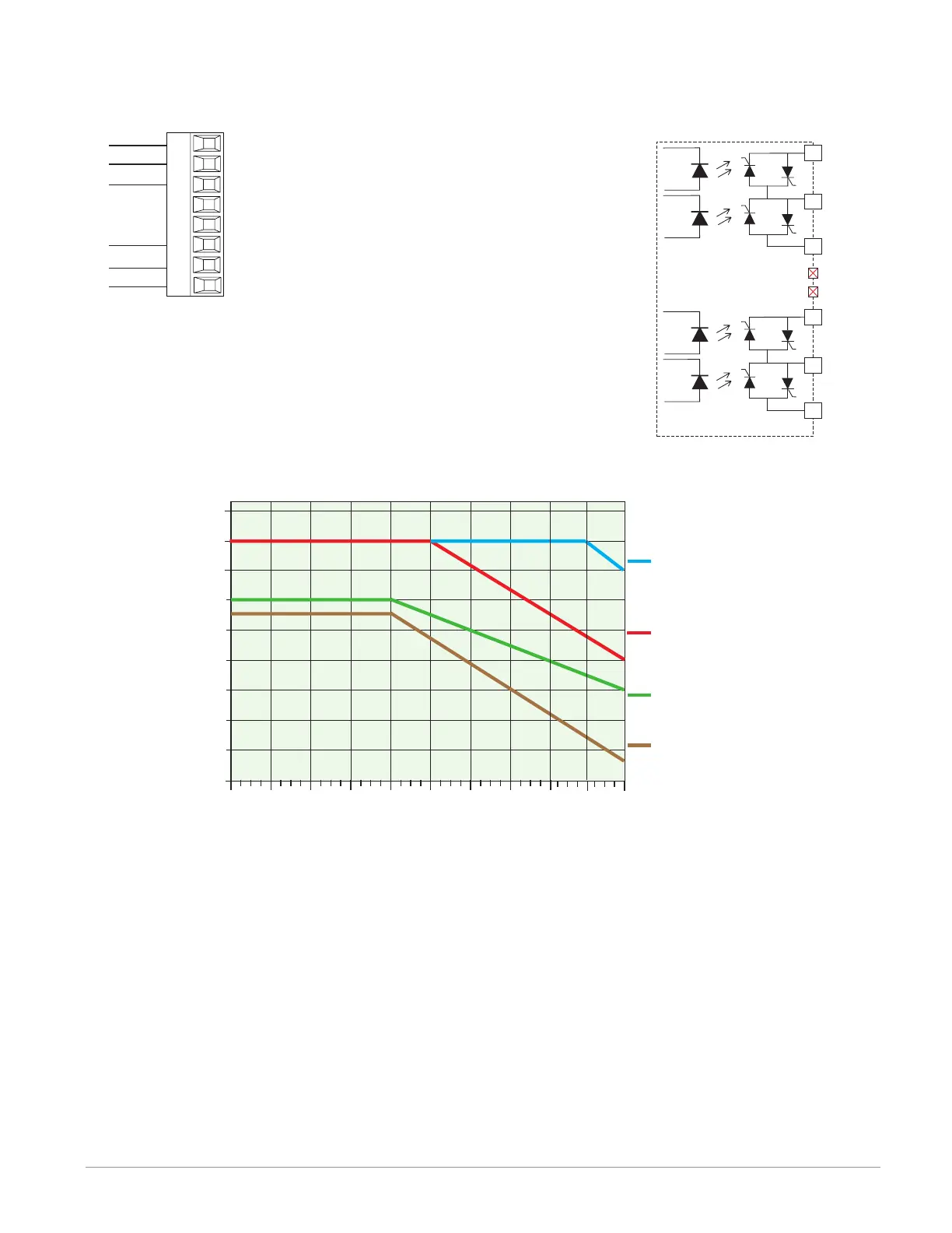
Four 2A Solid-State Relays, Form A (High Density) FMHA - LAAA - A _ _ _
normally open
common
L1
K1
L2
L3
K3
L4
normally open
normally open
common
normally open
• 2A at 20 to 264VÅ (ac) maximum resistive
load
• 50 VA 120/240VÅ (ac) pilot duty
• Optical isolation, without contact suppres-
sion
• Maximum off state leakage of 105 µA
• Output does not supply power.
• Do not use on dc loads.
• N.O., COM, N.O wiring (shared common)
between each set of outputs.
• See table below for maximum current out-
put.
K3
L3
L4
Normally
Normally
Common
K
1
L
1
L
2
Normally
Normally
Common
Not Used
Not Used
Quad 2 Amp SSR Derating Curve
All Outputs 100% Duty Cycle
Ambient Temperature (
o
C)
0.4
01510520
0.6
0.8
1.0
1.2
1.4
1.6
1.8
25 30 35 40
2.0
2.2
45 50
F4T with 2 FMs: 1 quad
input and 1 quad 2A
F4T with 2 FMs: 1 quad
input and 1 quad 2A
SSR FM. Outputs 1 and
3 on.
F4T with 5 FMs: 1 quad
2A SSR.
F4T with 6 FMs: 1 quad
2A SSR.
Anderson-Bolds ~ 216-360-9800

 Loading...


