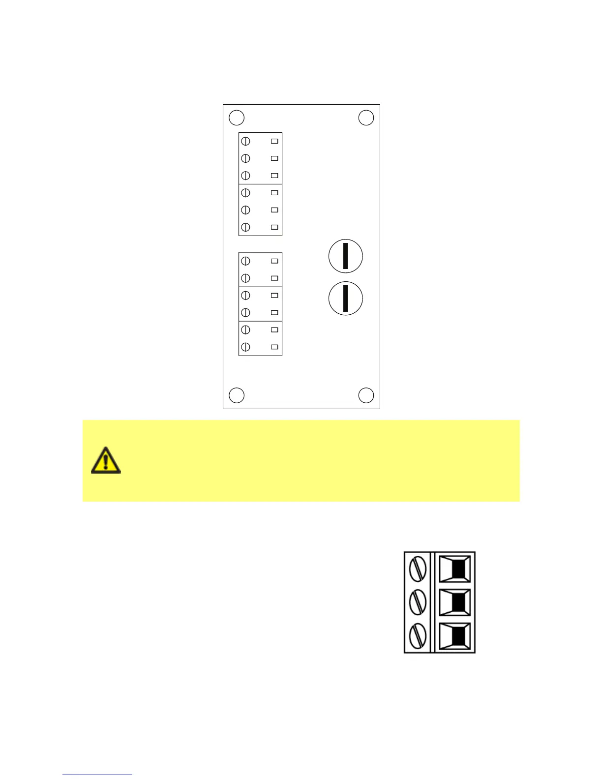
11.3 24Vrelay module pcb connectors
As you look at the module the pcb will appear in the same orientation as shown in the
diagram below.
Never apply mains power to the 4-20mA input, 4-20mA
output,+24VDC or stop contact terminals. Apply the correct signals to
the terminals shown below. Limit signals to the maximum values
shown. Do not apply voltage across other terminals. Permanent
damage, not covered by warranty, may result. The maximum load on
the relay contacts of this pump is 110VAC 5A or 30VDC 5A.
Alarm output (J5)
Connect the output device to the C (common) terminal
of the relay connector and either the N/C (normally
closed) or N/O (normally open) terminal as required.
This relay coil is energised when the pump has an alarm
condition.
Note: Alarm conditions are generated by system errors.
This alarm will not be operated for analogue signal
errors.
The default for Relay 1 is Alarm, on universal+ models
this output (1) can be configured in the control settings
menu.