The eight standard buttons are the following:
These arrows allow you to move through the menu options
and the data stored in memory.
allows to validate an option or enter in a menu.
always allows to come back to the main screen
(measuring screen).
allows to get back to an earlier menu or to cancel a selection.
allows to take print-screens anytime.
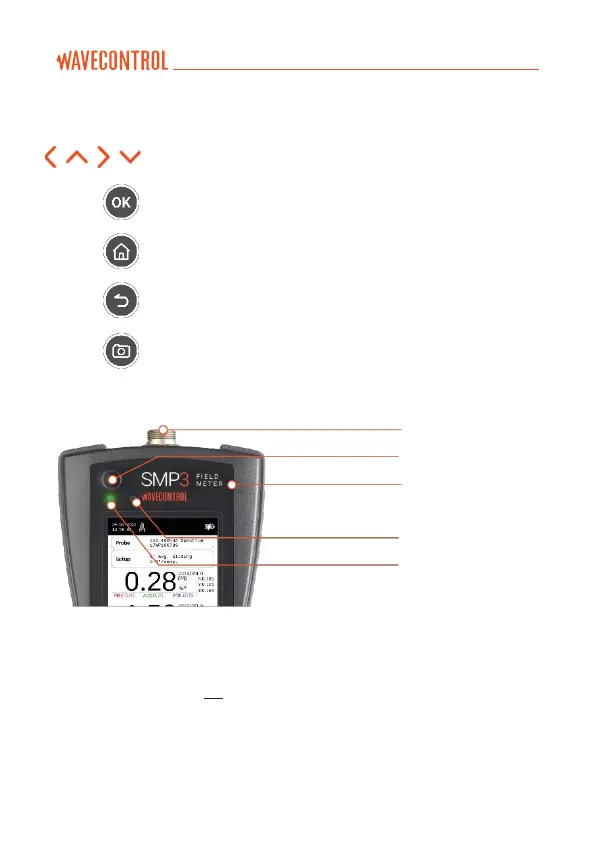
The top of the SMP3 holds the field probe connector.
Figure 3: Top of the SMP3
• Probe connector: (see 4.2).
• ON / OFF button: switches the equipment on and off.
• Status LED: when the unit is off, red means charging, green charged.
When the unit is on, green LED should be always on.
• Light sensor: allows to control the automatic screen back-light
intensity depending on ambient light.