127
CFW-08 OPTIONS AND ACCESSORIES
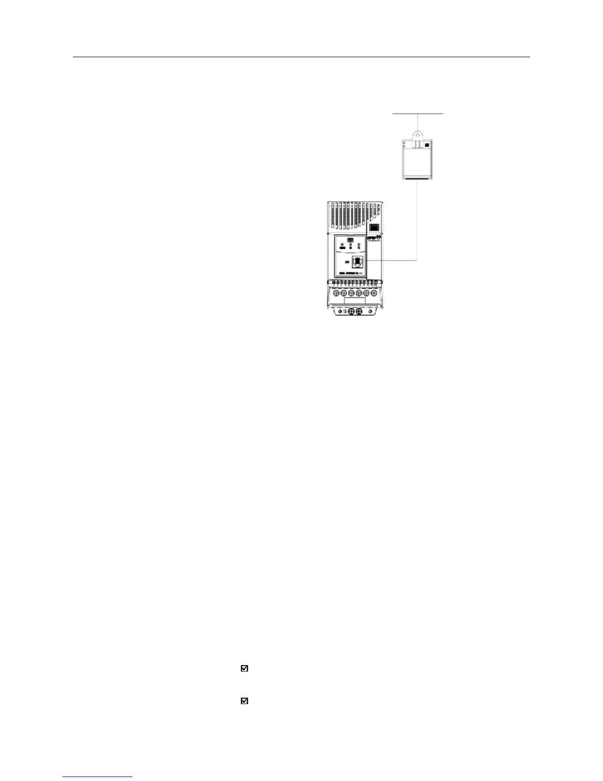
Figure 8.19 - Connection of the CFW-08 to a standard RS-485
communication network
CFW-08
RS-485
RS-232
MIW-02
POW
SER
WEG network
RS-485
8.15 RFI FILTER
The installation of frequency inverters requires some care in order to prevent
electromagnetic interferences (EMI).
This electromagnetic interference may disturb the operation of the inver-
ter itself or other devices, such as electronic sensors, PLCs, transducers,
radio equipment, etc. installed in the proximity.
To avoid these troubles, follow the installation instructions contained in
this Manual.
In this case, avoid the installation of electromagnetic noise generating
circuits, such as power cables, motors, etc. near to signal or control
cables.
Care should also be taken with the radiated interference, by shielding the
cables and the circuits that tend to emit electromagnetic waves and can
cause interference.
The electromagnetic interference can also be transmitted through power
supply line. This type of interference is minimized in the most cases by
capacitive filters which are already installed inside the CFW-08.
However, when inverters are installed in residential areas, the installation
of additional filter may be required.
These filters may be installed internally (on some types) or externally.
As defined in standards, the Class B filter has more attenuation capacity
than the Class A filter , thus being more suitable for residential areas.
Section 8.1 lists the available RFI filters with the respective inverter models.
The inverters with internal Class A filters have the same external dimensions
as the inverters without filter.
The external Class B filters must be installed between the power supply
line and the inverter input, as shown in Figure 8.18 below.
Instructions for the RFI filter installation:
Install the inverter and the filter on a metallic grounded plate as near to
each other as possible and ensure a good electrical contact between
the grounded plate and the inverter and filter frames.
For motor connection use a shielded cable or individual cables inside
a grounded metallic conduit.