157
CFW-08 OPTIONS AND ACCESSORIES
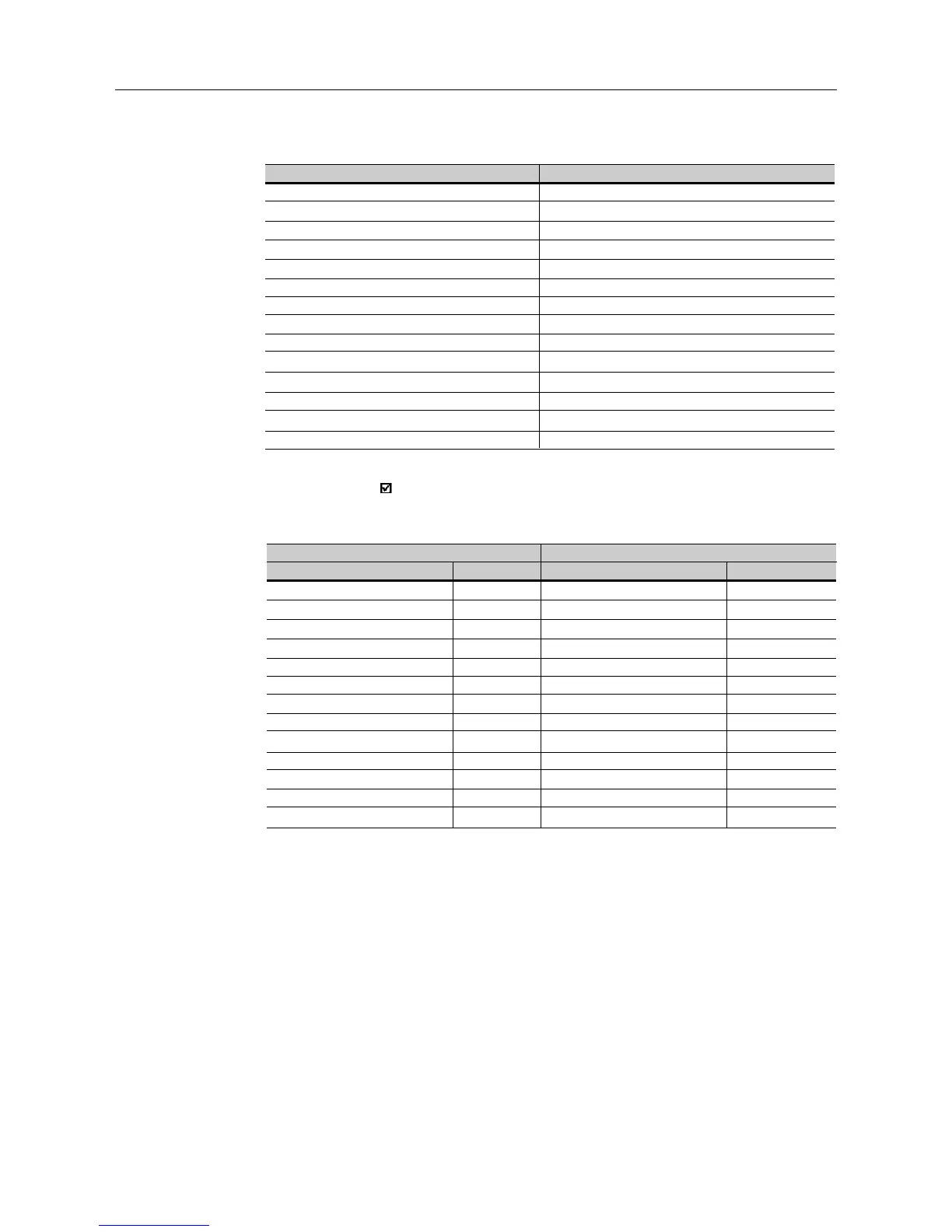
Query (Master)
Slave address
Function
Initial register address (byte high)
Initial register address (byte low)
Number of registers (byte high)
Number of registers (byte low)
Byte Count Field (number of data bytes)
Data 1 (high)
Data 1 (low)
Data 2 (high)
Data 2 (low)
etc...
CRC-
CRC+
Response (Slave)
Slave address
Function
Initial register address (byte high)
Initial register address (byte low)
Number of registers (byte high)
Number of registers (byte low)
CRC-
CRC+
Example: writing of the acceleration time (P100) = 1,0 s and deceleration
time (P101) = 2,0 s, of a CFW-08 at the address 20:
Query (Master)
Field Value
Slave address 14h
Function 10h
Initial register (byte high) 00h
Initial register (byte low) 64h
Number of registers (byte high) 00h
Number of registers (byte low) 02h
Byte Count 04h
P100 (high) 00h
P100 (low) 0Ah
P101 (high) 00h
P101 (low) 14h
CRC- 91h
CRC+ 75h
Response (Slave)
Field Value
Slave address 14h
Function 10h
Initial register (byte high) 00h
Initial register (byte low) 64h
Number of registers (byte high) 00h
Number of registers (byte low) 02h
CRC- 02h
CRC+ D2h
As the two parameters have a resolution of a decimal place for writing of
1.0 and 2.0 seconds, thus the values 10 (000Ah) and 20 (0014h) should
be transmitted.
8.20.3.7 Function 43 - Read
Device Identification
Auxiliary function that permits reading of the manufacturer, model and
version of the product firmware. It has following structure.