132
CFW-08 OPTIONS AND ACCESSORIES
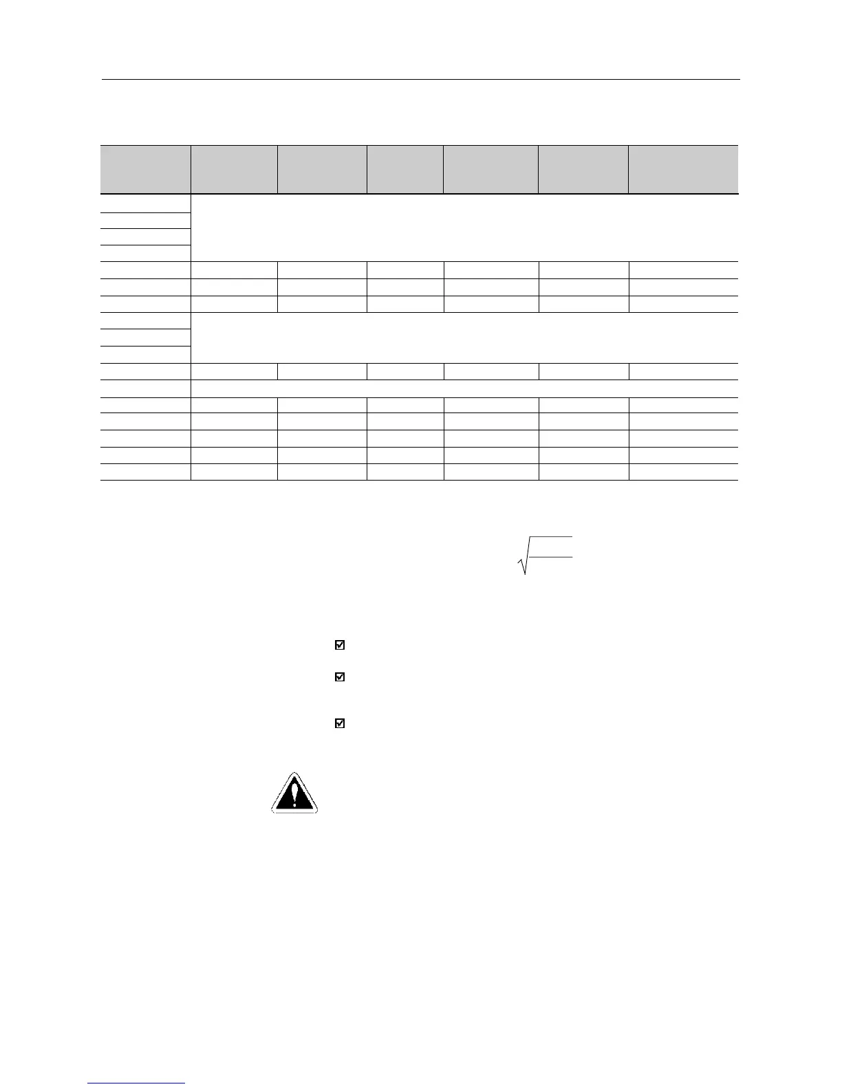
Inverter Model
1.6A / 200-240V
2.6A / 200-240V
4.0A / 200-240V
7.0A / 200-240V
7.3A / 200-240V
10A / 200-240V
16A / 200-240V
1.0A / 380-480V
1.6A / 380-480V
2.6A / 380-480V
2.7A / 380-480V
4.0A / 380-480V
4.3A / 380-480V
6.5A / 380-480V
10A / 380-480V
13A / 380-480V
16A / 380-480V
Maximum
Braking Current
10 A
15 A
20 A
6 A
6 A
8 A
16 A
24 A
24 A
RMS
Braking
Current (*1)
5 A
7 A
10 A
3.5 A
3.5 A
4 A
10 A
14 A
14 A
Recommended
Resistor
39 Ω
27 Ω
22 Ω
127 Ω
127 Ω
100 Ω
47 Ω
33 Ω
33 Ω
Recommended
Wiring
2.5 mm
2
/ 14 AWG
2.5 mm
2
/ 14 AWG
4 mm
2
/ 12 AWG
1.5 mm
2
/ 16 AWG
1.5 mm
2
/ 16 AWG
2.5 mm
2
/ 14 AWG
4 mm
2
/ 12 AWG
6 mm
2
/ 10 AWG
6 mm
2
/ 10 AWG
P
max
(Maximum
Resistor Power)
3.9 kW
6.1 kW
8.8 kW
4.6 kW
4.6 kW
6.4 kW
12 kW
19 kW
19 kW
P
rated
(Rated
Resistor Power)
0.98 kW
1.3 kW
2.2 kW
1.6 kW
1.6 kW
1.6 kW
4.7 kW
6.5 kW
6.5 kW
Braking not available
Braking not available
Braking not available
Table 8.5 - Recommended Braking Resistors
(*1) The rms braking current can be determined by:
I
rms
=
I
max
.
t
br
[min]
5
where t
br
corresponds to the sum of the braking times during the most
severe 5 minute cycle.
8.18.2 Installation
Connect the braking resistor between the +UD and BR power terminals
(refer to section 3.2.2).
Make this connection with a twisted pair. Run this cable separately
from any signal or control wire. Size the cable cross section according
to the application, by considering the maximum and the rms current.
If the braking resistor is installed inside the inverter panel, consider
the heat dissipated by the resistor when defining the panel ventilation.
DANGER!
The internal inverter braking circuit and the braking resistor can be damaged
when not correctly sized or when the line voltage exceeds the maximum
allowed value
In this case, the only guaranteed method to avoid burning the braking
resistor and eliminate risk of fire is the installation of a thermal overload
relay in series connected with the resistor and/or the installation of a
thermostat on the resistor body, wiring it in such a way that it disconnects
the inverter power supply in case of overheating, as shown in figure 8.22
below: