71
DETAILED PARAMETER DESCRIPTION
Read-Only Parameters Variables that can be viewed on the
display, but can not be changed by the
user.
Regulation Parameters Programmable values used by the
CFW-08 functions.
Configuration Parameters They define the inverter characteristics,
the functions to be executed, as well as
the input/output functions of the control
board.
Motor Parameters Data about the applied motor: data
indicated on the motor nameplate and
those obtained during the running of the
self-tuning routine.
Special Function Parameters Here are included parameters related to
special functions, like PID regulator.
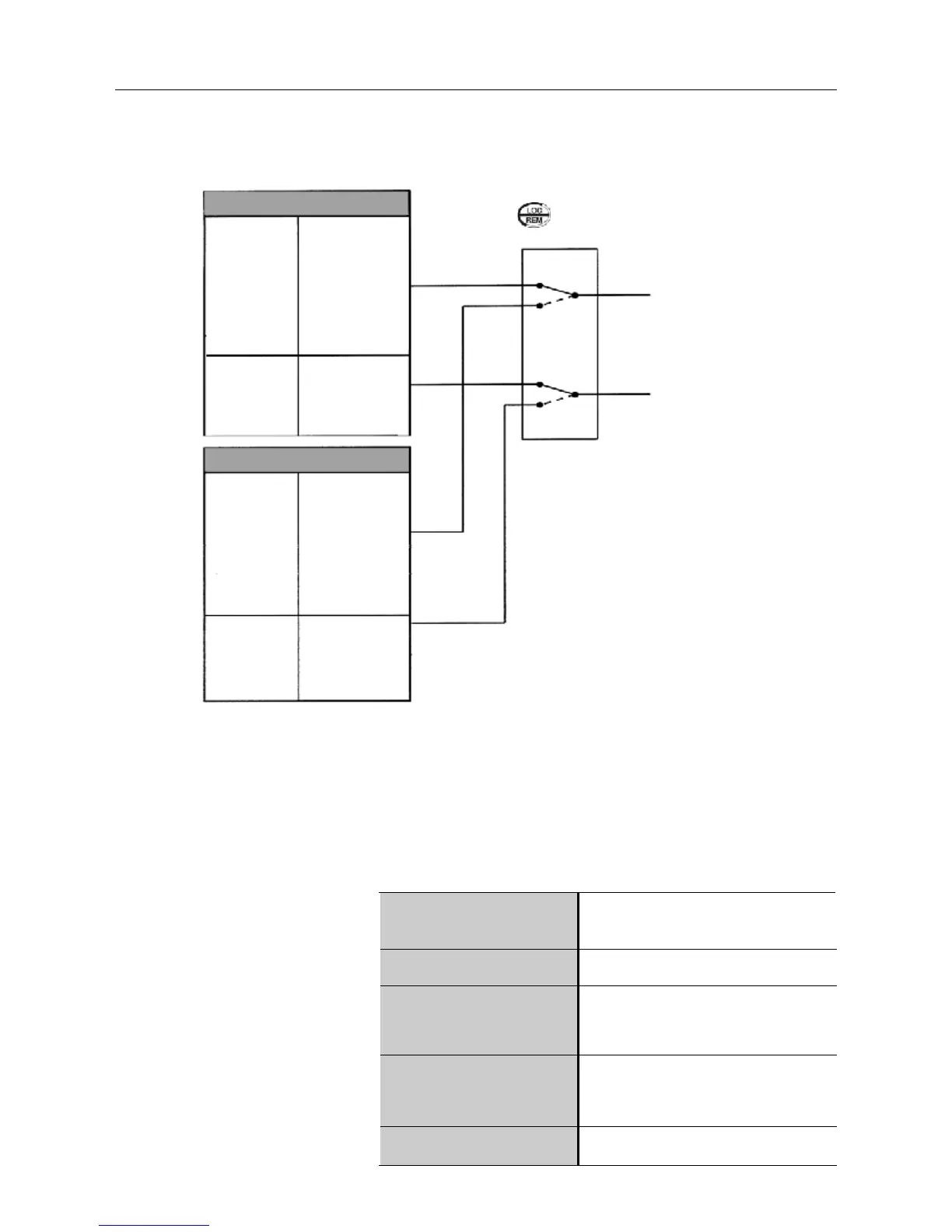
Figure 6.3 - Block diagram of the local and remote operation mode
LOCAL
Frequency
Reference
P221
Controls
P229 (stop/run,
FWD/REV and
JOG)
0 Keypad
(HMI-CFW08-P and
HMI-CFW08-RS)
1 AI1
2 or 3 AI2
4EP
5 Serial
6 Multispeed
7 Add AI
8 Add AI>0
0 HMI-CFW08-P
keypad
1 Bornes XC1 (DIs)
2 Serial or HMI-
CFW08-RS keypad
REMOTE
Frequency
Reference
P222
Controls
P230 (start/stop,
FWD/REV and
JOG)
0 Keypad
(HMI-CFW08-P and
HMI-CFW08-RS)
1 AI1
2 or 3 AI2
4EP
5 Serial
6 Multispeed
7 Add AI
8 Add AI>0
0 HMI-CFW08-P
keypad
1 Termin. XC1 (DIs)
2 Serial or
HMI-CFW08-RS
keypad
REFERENCE
COMMANDS
Local/Remote Selection (P220)
+
Local/Remote Command
( , DI, serial, etc)
6.3 PARAMETER
LISTING
In order to simplify the explanation, the parameters have been grouped by
characteristics and functions:
F*