EasyManuals Logo

WEG CFW08 Vector inverter User Manual

WEG CFW08 Vector inverter
167 pages
To Next Page IconTo Next Page
To Previous Page IconTo Previous Page
Page #124 background imageLoading...
Page #124 background image
123
CFW-08 OPTIONS AND ACCESSORIES
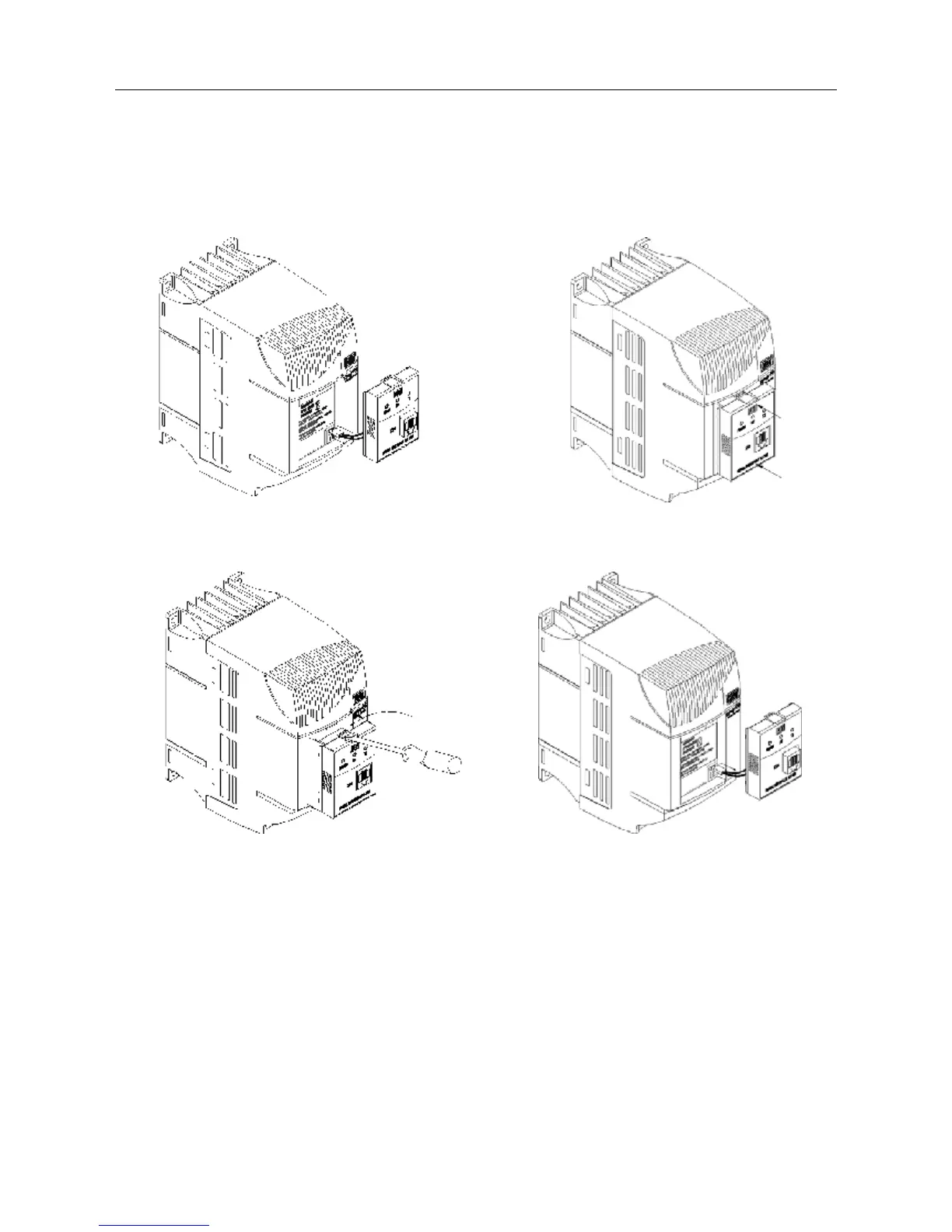
8.9.1 Instructions for
KCS-CFW08
Insertion/Removal
-Connect the cable of the
communication module to XC5
- Place the communication
module as shown in figure above.
- Press it.
(a) Insertion
- Use a screwdriver to unlock the
communication module.
- Remove the module by pulling it
on the lateral sides
(b) Removing
- Remove the cable from the XC5
connector.
Figure 8.14 - Insertion and removal of the serial communication module RS-232 KCS-CFW08
8.10 KSD-CFW08
The complete kit, that enables the connection of the CFW-08 to a PC via
RS-232 contains:
- Serial communication module RS-232 (KCS-CFW08);
- 3m cable RJ-6 for the DB9;
- Software “SUPERDRIVE” for Windows 95/98, Windows NT
Workstation V4.0 (or later operational system), that enables the
CFW-08 programming, operating and monitoring.

Table of Contents

Questions and Answers:

Question and Answer IconNeed help?

Do you have a question about the WEG CFW08 Vector inverter and is the answer not in the manual?

WEG CFW08 Vector inverter Specifications

General IconGeneral
Frequency Range0 to 300 Hz
Overload Capacity150% for 60 seconds
Protection DegreeIP20
CommunicationRS485, Modbus RTU
Voltage200 V to 240 V
Control ModeVector Control
Ambient Temperature-10°C to 50°C
Input Frequency50 Hz / 60 Hz
Output Voltage0 to input voltage
BrakingDynamic braking resistor (optional)
Protection FeaturesOvercurrent, overvoltage, undervoltage, overtemperature
Operating Temperature-10°C to 50°C
Cooling MethodForced air cooling (fan)
Humidity5% to 90% non-condensing

Related product manuals