72
DETAILED PARAMETER DESCRIPTION
Range
[Factory Setting]
Parameter Unit Description / Notes
P000 0...999
Access Parameter [ 0 ]
1
6.3.1 Access and Read Only Parameters - P000 ... P099
P002 0...6553
Frequency [ - ]
Proportional Value 0.01 (<100.0);
0.1 (<1000);
1 (>999.9)
P003 0...1.5 x I
nom
Output Current [ - ]
(Motor) 0.01A (<10.0A);
0.1A (>9.99A)
P004 0...862V
DC Link Voltage [ - ]
1V
Releases the access to change the parameter values.
The password is 5.
The use of the password is always active.
Indicates the value of P208 x P005.
When the vector control mode is used (P202=2), P002 indicates
the actual motor speed in rpm.
In case of different scales and units, use P208.
Indicates the inverter output current in Amps. (A).
Indicates the inverter DC Link voltage in Volts (V).
P005 0...300Hz
Output Frequency [ - ]
(Motor) 0.01Hz (<100.0Hz);
0.1Hz (>99.99Hz)
Indicates the inverter output frequency in Hertz (Hz).
P007 0...600V
Output Voltage [ - ]
(Motor) 1V
Indicates the inverter output voltage in Volts (V).
P008 25...110
o
C
Heatsink Temperature [ - ]
1
o
C
Indicates the current power at the heatsink in Celsius degrees
(°C).
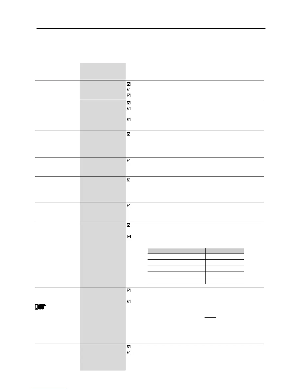
The inverter overtemperature protection (E04) acts when
heatsink temperature reaches:
Inverter
1.6-2.6-4.0-7.0A/200-240V
1.0-1.6-2.6-4.0A/380-480V
7.3-10-16A/200-240V
2.7-4.3-6.5-10A/380-480V
13-16A/380-480V
P008 [°C] @ E04
103
90
90
103
103
P009 0.0...150.0%
Motor Torque [ - ]
0.1%
Indicates the torque developed by motor in, in percent (%) relating
to the set rated motor torque.
The rated motor torque is defined by the parameters P402
(motor speed) and P404 (motor power). I.e.:
where T
nom
is given in kgf.m, P
nom
is the rated motor power in watts-
HP - (P404), and n
nom
is the rated motor speed in rpm - P402.
T
nom
= 716 .
P
nom
n
nom
P014 00...41
Last Fault [ - ]
-
Indicates the code of the last occured fault.
Section 7.1 shows a list of possible faults, their code numbers
and possible causes.
This
parameter is only
shown in vector
control
(P202=2)