EasyManuals Logo

WEG CFW08 Vector inverter User Manual

WEG CFW08 Vector inverter
167 pages
To Next Page IconTo Next Page
To Previous Page IconTo Previous Page
Page #119 background imageLoading...
Page #119 background image
118
CFW-08 OPTIONS AND ACCESSORIES
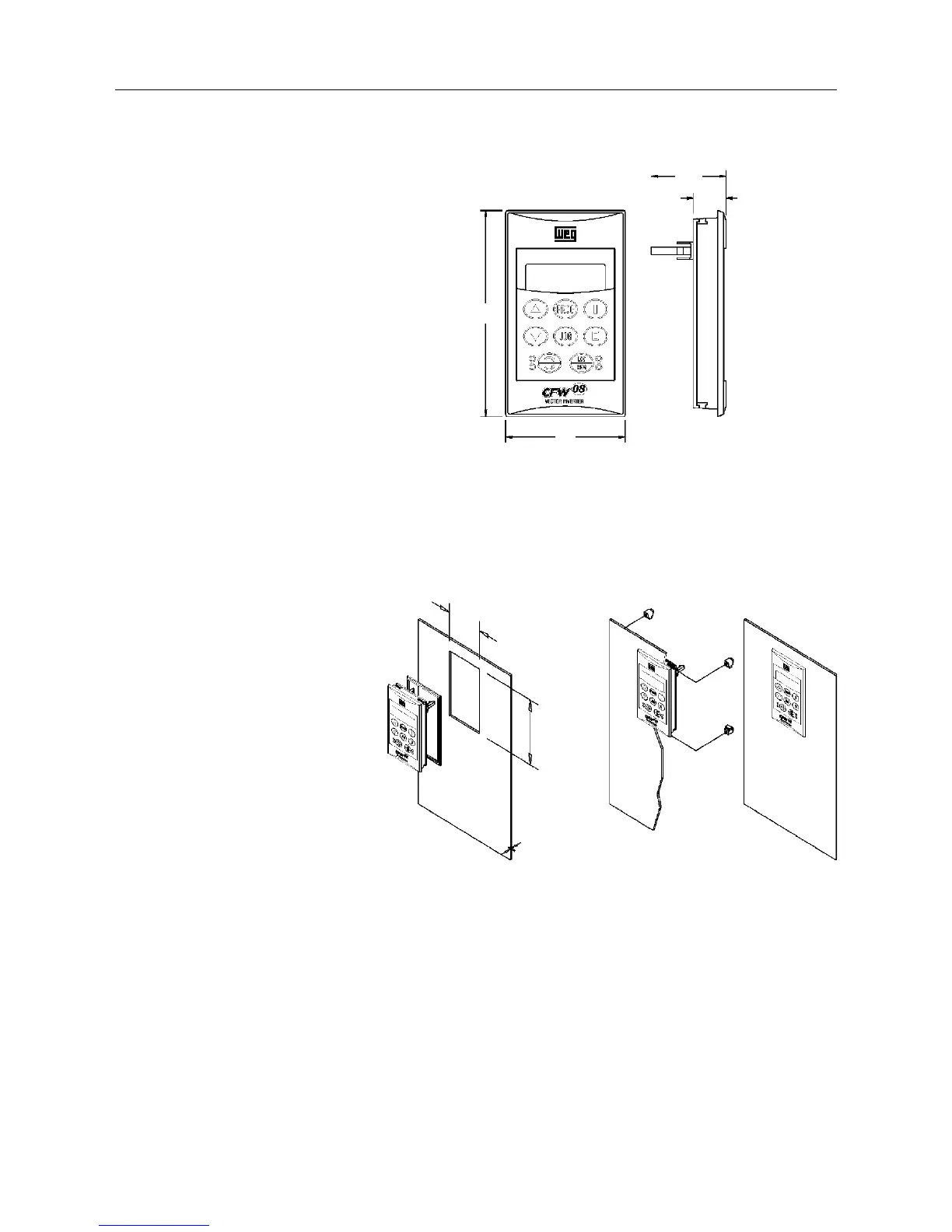
Figure 8.4 - Dimensions of the HMI-CFW08-RP
8.3.1 HMI-CFW08-RP
Installation
The HMI-CFW08-RP can be installed directly on the panel door (0,12in),
as shown in the figures below:
Figure 8.5 - Installation of the HMI-CFW08-RP
8.4 MIP-CFW08-RP
Isolation interface: Isolation interface installed in the inverter instead of
the standard keypad only when the remote parallel keypad (HMI-CFW08-
RP) is used.
The procedures for insertion and removing of the MIP-CFW08-RP are
similar to those shown in figure 8.13 for the KCS-CFW08 module.
58
98
15.9
36.3
52mm
(2.05in)
92mm
(3.62in)
Max. 3mm
(0.12in)

Table of Contents

Questions and Answers:

Question and Answer IconNeed help?

Do you have a question about the WEG CFW08 Vector inverter and is the answer not in the manual?

WEG CFW08 Vector inverter Specifications

General IconGeneral
Frequency Range0 to 300 Hz
Overload Capacity150% for 60 seconds
Protection DegreeIP20
CommunicationRS485, Modbus RTU
Voltage200 V to 240 V
Control ModeVector Control
Ambient Temperature-10°C to 50°C
Input Frequency50 Hz / 60 Hz
Output Voltage0 to input voltage
BrakingDynamic braking resistor (optional)
Protection FeaturesOvercurrent, overvoltage, undervoltage, overtemperature
Operating Temperature-10°C to 50°C
Cooling MethodForced air cooling (fan)
Humidity5% to 90% non-condensing

Related product manuals