40
INSTALLATION AND CONNECTION
5) Relays, contactors, solenoids or eletromagnetic braking coils installed
near inverters can generate interferences in the control circuit. To
eliminate this interference, connect RC suppressor in parallel with the
coils of AC relays. Connect free-wheeling diode in case of DC relays.
6) When external keypad (HMI) is used (refer to Chapter 8), separete
the cable that connects the keypad to the inverter from other cables,
maintaining a minimum distance of 4 in (10 cm) between them.
7) When analog reference (AI1 or AI2) is used and the frequency
oscillates (problem caused by eletromagnetic interference)
connect XC1:5 to the inverter heatsink.
3.2.5 Typical Terminal
Connections
Connection 1 - Keypad Start/Stop (Local Mode)
With the factory default programming, you can operate the inverter in
local mode with the minimum connections shown in Figure 3.4 (Power)
and without control connections. This operation mode is recommended
for users who are operating the inverter for the first time. Note that there is
no need of connection of control terminals.
For start-up according to this operation mode, refer to Chapter 4.
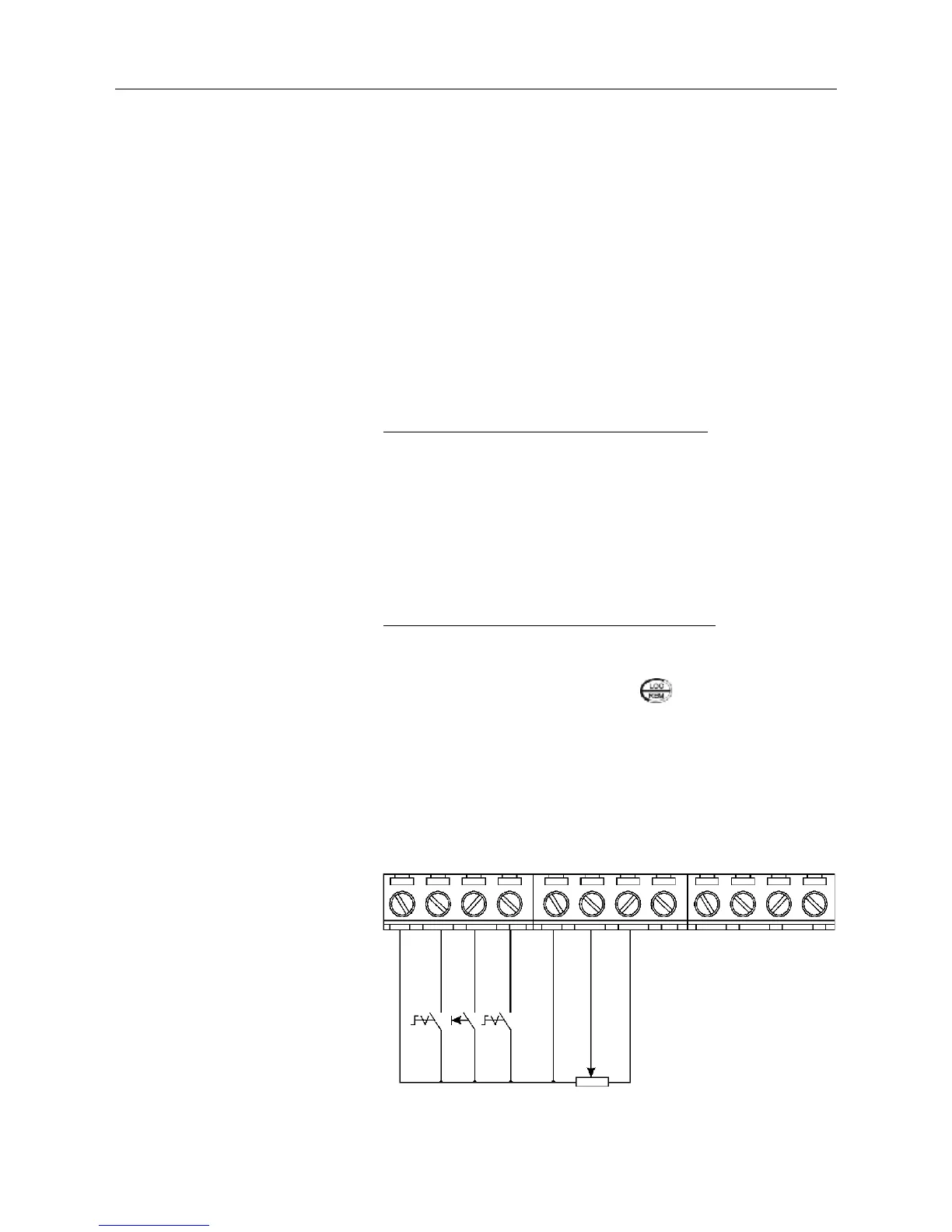
Connection 2 - 2-Wire Start/Stop (Remote Mode)
Valid for factory default programming and inverter operating in remote
mode. For the factory default programming, the selection of the operation
mode (local/remote) is made via the key (default is local).
S1: FWD / REV
S2: Reset
S3: Start / Stop
R1: Potentiometer for
speed setting
Figure 3.12 - XC1 wiring for connection 2
No Function or General Enabling
1234 5678 9101112
DI2 - FWD / REV
DI3 - Reset
COM
AI1
+10V
AI2
AO1
NC
Common
NO
DI4 - No Function or Start/Stop
R1
S3
S2
S1
5k
≥