64
KEYPAD (HMI) OPERATION
NOTE!
(1) For parameters that can be changed with the motor running, the
inverter will use the new value immediately after it has been set. For
parameters that can be changed only with motor stopped, the inverter
will use this new value only after the key is pressed.
(2) By pressing the key after the reprogramming, the new
programmed value will be stored automatically and will remain stored
until a new value is programmed.
5.2.4 Parameter Viewing and
Programming
All CFW-08 settings are made through parameters. The parameter are
shown on the display by the letter P followed by a number:
Exmple (P101):
101 = Parameter Number
Each parameter is associated with a numerical value (parameter value),
that corresponds to the selected option among the available ones for this
parameter.
The parameter values define the inverter programming or the value of a
variable (e.g.: current, frequency, voltage).For inverter programming you
should change the parameter content(s).
To allow the reprogramming of any parameter value (except for P000 and
P121) it is required to set P000 = 5.
Otherwise you can only read the parameter values, but not reprogram
them. For more details, see P000 description in Chapter 6.
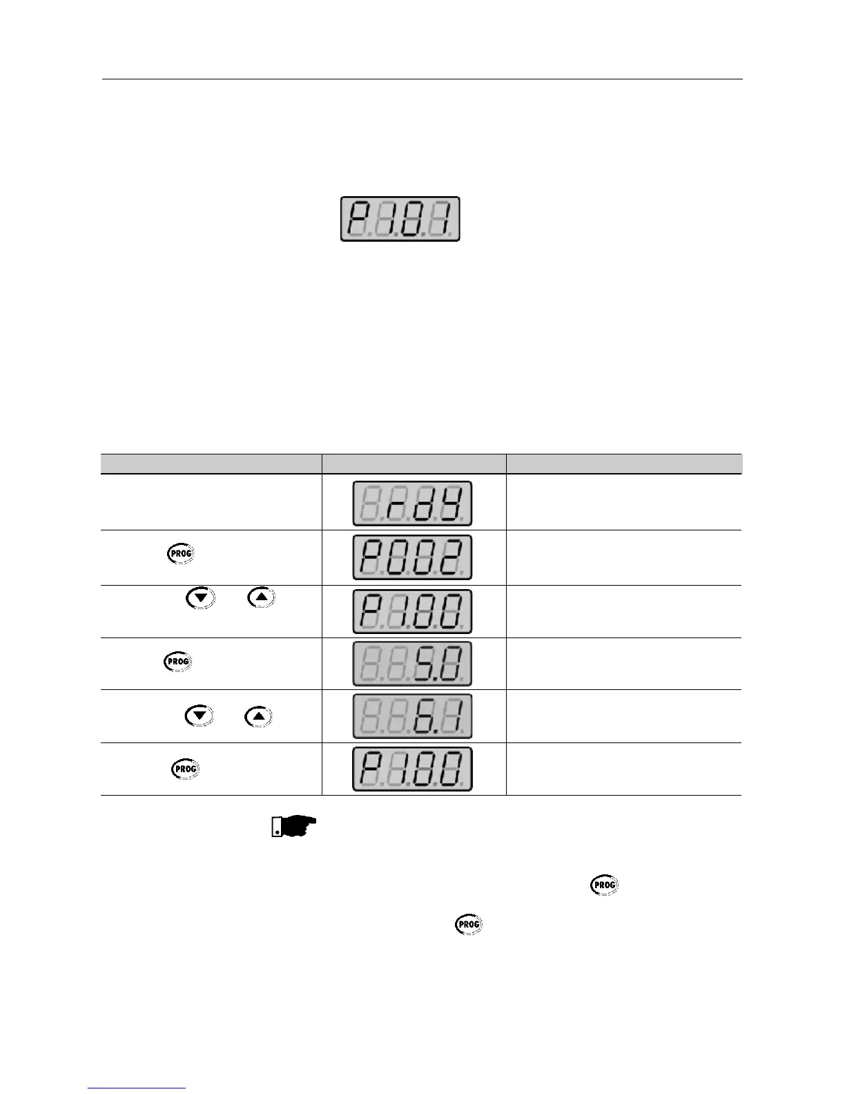
ACTION HMI DISPLAY DESCRIPTION
Turn ON the inverter
Press the key
Use the keys and to
reach P100
Press the key
Use the keys and keys
Press the key
Inverter is ready to be started
Select the desired parameter
Numerical value associated with the
parameter
(4)
Set the new desired value
(1) (4)
(1) (2) (3)