59
START-UP
NOTE!
The last speed reference value set via key and keys
is saved.
If you wish to change this value before enabling of inverter, change the
value of the Parameter P121 - Keypad Reference;
The self-tuning routine can be cancelled by pressing the key.
NOTES:
(1) If during the running of the Self-Tuning Routine the display shows E14,
this means that the motor parameters were not acquired correctly by the
inverter. The most common reason for this fault may be that the motor has
not been coupled to the inverter output. However motors with very lower
currents than the used inverter, or incorrect motor connection may also
cause the fault E14. In this case, operate the inverter in V/F mode (P202=0).
When the motor is not connected and the fault condition E14 is indicated,
proceed as follows:
Switch off the inverter. Wait at least 5 minutes to allow a complete discharge
of the capacitors.
Connect the motor to the inverter output.
Switch on the inverter.
Set P000=5 and P408=1.
Follow from now on the start-up procedures described in Section 4.3.3.
(2) For each inverter type, the parameters P399...P407 are set automatically
to the rated motor data, considering a standard WEG motor, IV poles,
60Hz.
When different motors are used, you must set the parameters manually,
according to the motor nameplate data.
(3) If the direction of rotation of the motor is not correct, switch off the inveter.
Wait at least 5 minutes to allow a complete discharge of the capacitors
and then swap any two wires at the motor output.
(4) If fault E01 occurs during deceleration, you must increase the deceleration
time at P101/P103.
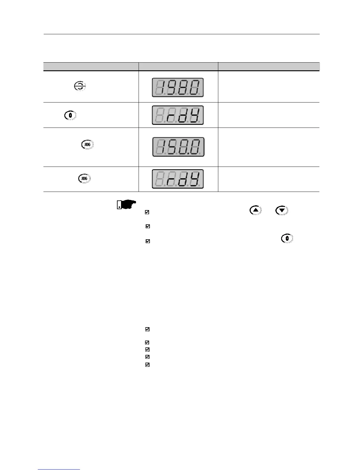
ACTION HMI DISPLAY DESCRIPTION
Press the key
Press key
Press the key and hold it
depresed
Release the key
Motor decelerates
(4)
tom 0 rpm and the
reverses the direction of rotation
accelerating back to 1980rpm
Motor decelerates down to 0 rpm
Motor accelerates from 0 rpm up to the
JOG speed set at P122.
Ex: P122 = 5.00Hz that corresponds to
150rpm for IV-pole motor.
Reverse (CCW) direction of rotation
Motor decelerates down to 0 rpm