82
DETAILED PARAMETER DESCRIPTION
Range
[factory Setting]
Parameter Unit Description / Notes
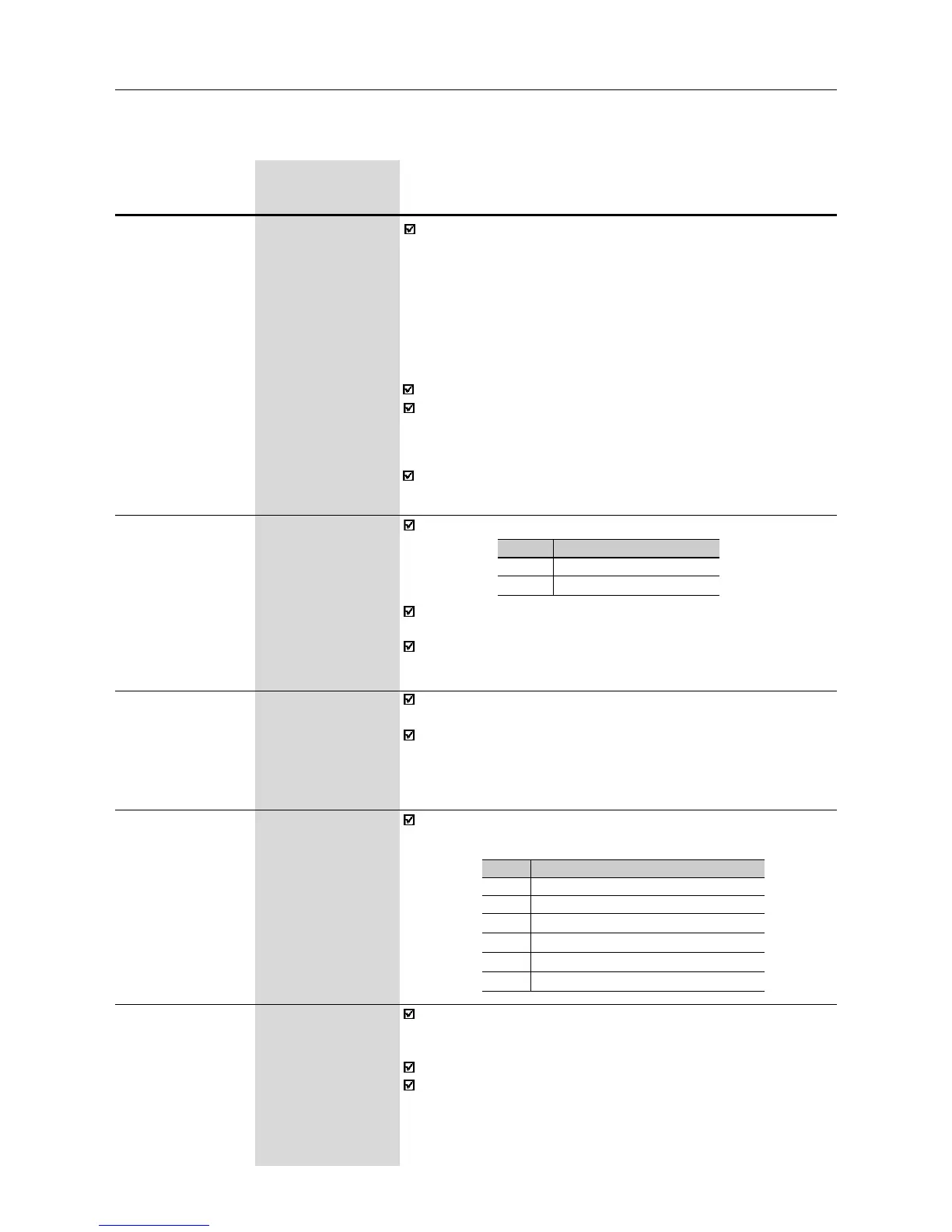
Selects or not the special function of the PID regulator.
P203
(1)
0...1
Special Function [ 0 - None ]
Selection -
P203
0
1
Special function
None
PID regulator
See detailed description of PID regualator parameters (P520...P528)
in Section 6.3.5.
When P203 is changed to 1, P265 is changed automatically to 15
(DI3 = manual/automatic).
Programs all parameters to the standard factory default, when
P204=5.
The parameters P142 (max. output voltage), P145 (field weakening
frequency), P295 (rated current), P308 (inverter address) and P399
to P407 (motor parameters) are not changed when the factory default
parameters are loaded through P204=5.
P204
(1)
0...5
Load Factory [ 0 ]
setting -
Selects which of the parameters listed below will be shown on the
display as a default after the inverter has been powered up.
P205
(1)
0...6
Display [ 2 - P002 ]
Default -
Selection
P205
0
1
2
3
4, 5
6
Read Parameter
P005 [Output Frequency (Motor)]
P003 [Output Current (Motor)]
P002 (Value Proportional to Frequency)
P007 [Output Voltage (Motor)]
Not used
P040 (PID Process Variable)
In the event of a fault trip, except for E14, E24 and E41, the inverter
can initiate an automatic reset after the time given by P206 is
elapsed.
If P206 2 Auto-Reset does not occur.
If after Auto-Reset the same fault is repeated three times
consecutively, the Auto-Reset function will be disabled. A fault is
considered consecutive if it happens again within 30 seconds after
the Auto-Reset. Thus if a fault occurrs four times consecutively,
this fault remains indicated permanently (and inverter disabled).
P206 0...255s
Auto-Reset Time [ 0 ]
1s
≥
≥
(1)
This parameter can be changed only with the inverter disabled (motor stopped).
The vector control allows a better performance regarding to torque
and speed control. The CFW-08 vector control operates without
motor speed sensor (sensorless). It must be applied when following
performances are required:
- better dynamics (faster accelerations and stoppings);
- when a more accurate speed control is required;
- when high torques at low speeds are required ( 5Hz).
Examples: in positioning, such as load moving, packing machines,
pumps, dosing machines, etc.
The vector control can not be used in multimotor applications.
The performance of the vector control with a switching frequency of
10kHz is not so good as when a switching frequency of 5kHz or
2.5kHz is used. It is not possible to use a vector control with a
switching frequency of 15kHz.
For more details about the vector control, refer to Item 6.2.3.