1
QUICK REFERENCE OF PARAMETERS AND FAULTS
Param. Description Adjustable range Factory
setting
Page
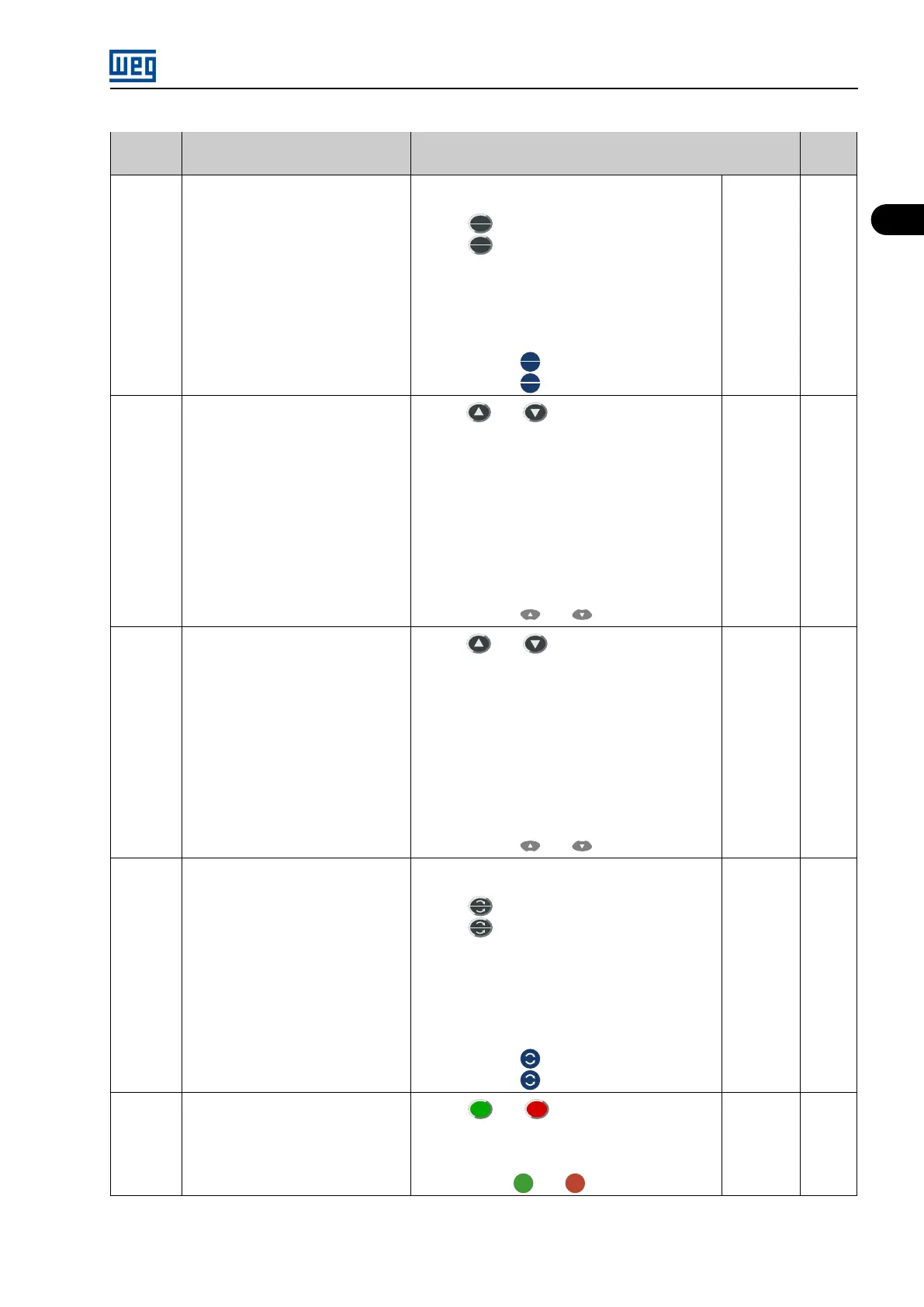
P0220
(1)
LOCAL/REMOTE selection source 0 = Always LOCAL
1 = Always REMOTE
2 = HMI
key (LOCAL default)
3 = HMI
key (REMOTE default)
4 = Digital Inputs DI2...DI10 (P0264...P0272)
5 = Serial (LOCAL Default)
6 = Serial (REMOTE Default)
7 = Fieldbus (LOCAL Default)
8 = Fieldbus (REMOTE Default)
9 = LOCAL PLC
10 = REMOTE PLC
11 = Graphic HMI
key (LOCAL Default)
12 = Graphic HMI
key (REMOTE Default)
11 5-35
P0221
(1)
Speed reference selection LOCAL situ-
ation
0 = Key and of service HMI
1 = Analog Input AI1’ (P0234 to P0236)
2 = Analog Input AI2’ (P0237 to P0240 and P0248)
3 = Analog Input AI3’ (P0241 to P0244).
4 = Analog Input AI4’ (P0245 to P0247)
5 = Sum of Analog Inputs (AI1’ + AI2’) > 0 (Negative
values are zeroed)
6 = Sum of Analog Inputs (AI1’ + AI2’)
7 = Electronic Potentiometer (E.P.)
8 = Multispeed (P0124 to P0131)
9 = Serial
10 = Fieldbus
11 = Analog Input AI5’ (P0721 to P0724)
12 = PLC
13 = Graphic HMI and key
13 5-36
P0222
(1)
Speed reference selection REMOTE sit-
uation
0 = Key and of service HMI
1 = Analog Input AI1’ (P0234 to P0236)
2 = Analog Input AI2’ (P0237 to P0240 and P0248)
3 = Analog Input AI3’ (P0241 to P0244).
4 = Analog Input AI4’ (P0245 to P0247)
5 = Sum of Analog Inputs (AI1’ + AI2’) > 0 (Negative
values are zeroed)
6 = Sum of Analog Inputs (AI1’ + AI2’)
7 = Electronic Potentiometer (E.P.)
8 = Multispeed (P0124 to P0131)
9 = Serial
10 = Fieldbus
11 = Analog Input AI5’ (P0721 to P0724)
12 = PLC
13 = Graphic HMI and key
0 5-36
P0223
(1)
Forward/Reverse Selection LOCAL Sit-
uation
0 = Always forward
1 = Always reverse
2 = HMI key (Forward default)
3 = HMI key (Reverse default)
4 = Digital Input DI2 (P0264 = 0)
5 = Serial (Forward default)
6 = Serial (Reverse default)
7 = Fieldbus (Forward default)
8 = Fieldbus (Reverse default)
9 = AI4 Polarity
10 = Forward PLC
11 = Reverse PLC
12 = Graphic HMI key (Forward)
13 = Graphic HMI key (Reverse)
12 5-36
P0224
(1)
Start/Stop Selection LOCAL Situation 0 = HMI
and
keys
1 = Digital input DIx
2 = Serial
3 = Fieldbus
4 = PLC
5 = Graphic HMI
and
key
5 5-37
MVW3000 | 1-5