Repair information and repair instructions 17
10. Screw the swivel screw connection 42 onto the
pressure gauge 6 using an open-ended span-
ner (SW 7).
Take care to ensure the correct installation posi-
tion. The tube must not protrude beyond the hous-
ing afterwards.
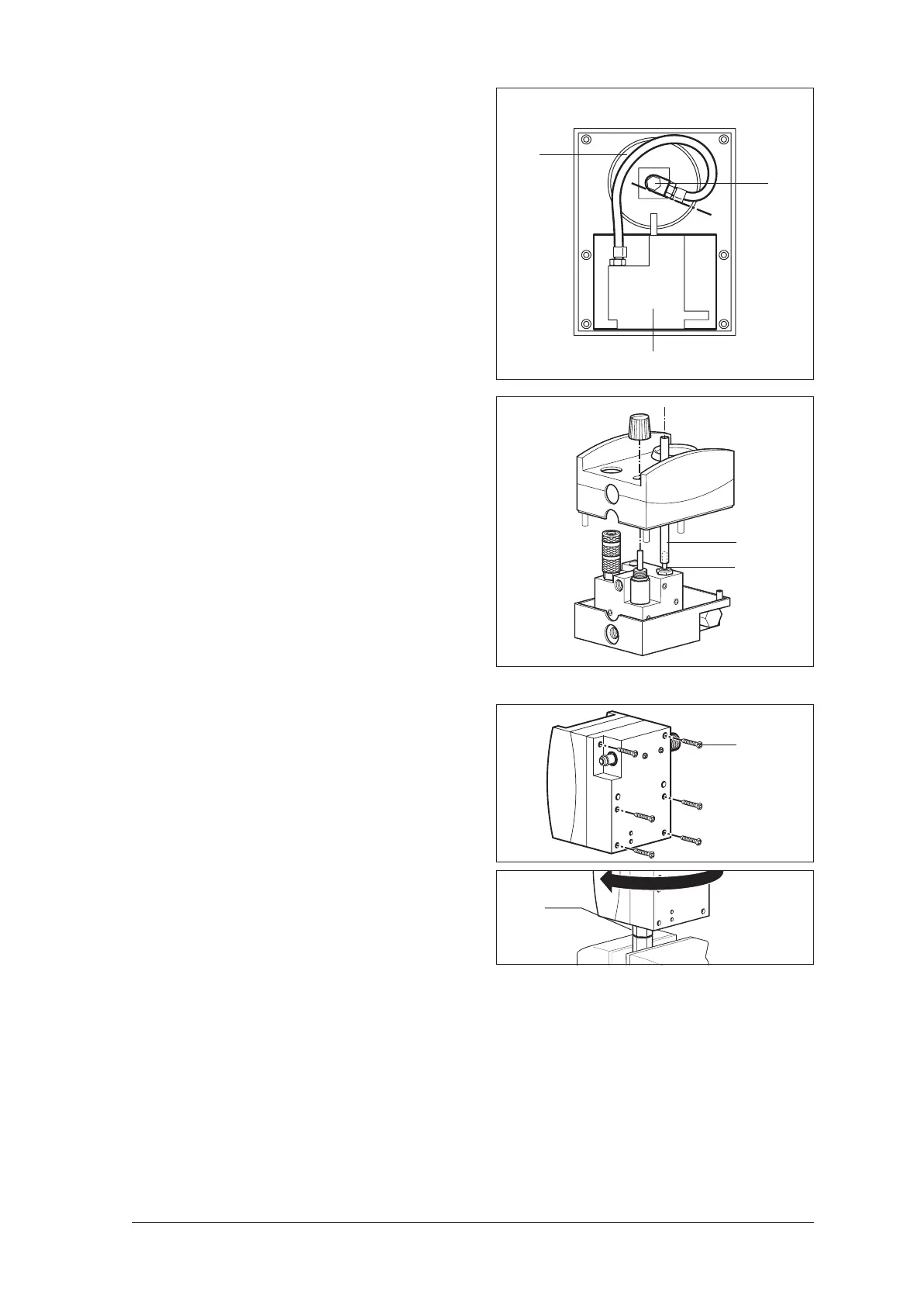
11. Move the toggle switch 20 to the central posi-
tion and place the guide pipe over it. The
guide pipe holds the toggle switch in position,
allowing you to fit the upper housing section
more easily.
12. Carefully push the upper housing section over
the guide pipe onto the base section.
Make sure the tubes are not pinched.
13. Remove the guide pipe.
14. Turn the device round and screw the housing
together using the six screws 32.
15. Clean the threaded connection for
inhalation 11 and the threaded hole.
16. Connect the module to the O
2
supply and
switch the toggle switch to I. Turn up the pres-
sure control so that the threaded hole is blown
clean.
17. Wet the threaded connection 11 with Loctite
245, and screw it into the pneumatic block us-
ing the special locknut tool.
42
6
Pneumatic block
Illustration of subsequent installation position
Guide pipe
20
32
11