32 Interface MODULE
6.5 Interface MODULE
6.5.1 Replacing the sieve in the oxygen inlet
See ”6.2.1 Replacing the sieve in the oxygen inlet“ on page 13.
6.5.2 Replacing the O-ring in the oxygen outlet
See ”6.2.2 Replacing the O-ring in the oxygen outlet“ on page 14.
6.5.3 Dismantling the housing
See ”6.2.3 Dismantling the housing“ on page 14, with two exceptions:
1. Steps 1. to 4. do not apply, since Interface
MODULE does not have a knob.
2. Step 14. do not apply, since Interface MOD-
ULE does not have a connection for inhalation.
6.5.4 Assembling the housing
See ”6.2.4 Assembling the housing“ on page 16, with six exceptions:
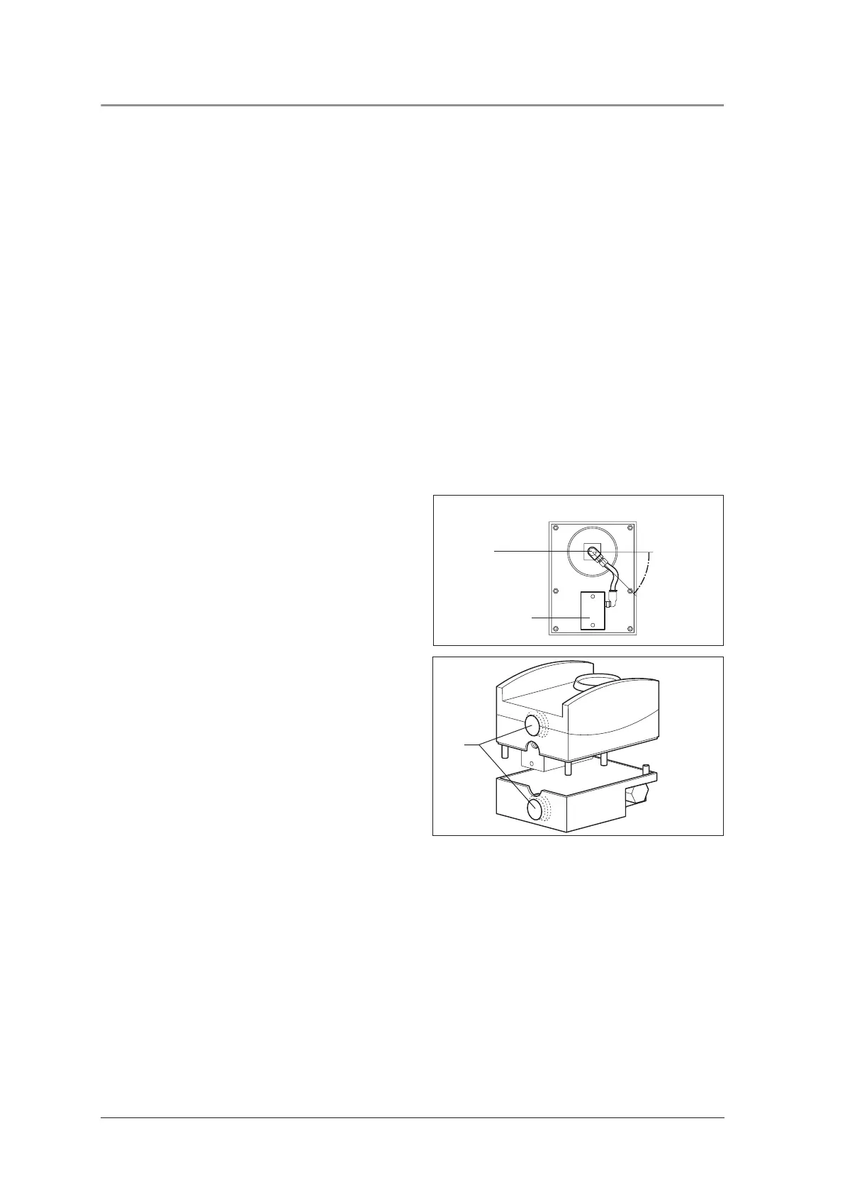
1. Re: step 10.:
The swivel screw connection 42 must be lying at
an angle of approx. 45° to the horizontal.
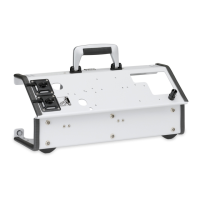
2. Re: step 4.:
A blind plug 35 is placed into both the top side
and the underside of the device. The flattened
side of the blind plug must be pointing towards
the base of the device in both cases.
3. Step 11. does not apply, since Interface
MODULE does not have a toggle switch.
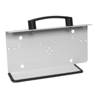
4. Re: step 12.:
During assembly of the two halves of the hous-
ing, the two pins on the upper section of the
housing must snap into the holes in the housing
base section.
5. Steps 13. to 23. do not apply, since Interface
MODULE does not have a knob.
6. As Interface MODULE does not have a toggle
switch, the upper housing section 15 may be
mounted on the housing base section 16
without guide pipes.
≈ 45°
42
Pneumatic block
Illustration of subsequent installation position
35