INSTALLATION AND MAINTENANCE MANUAL
LYNX E1 FAMILY
LICENSED & SPREAD SPECTRUM RADIOS
JUNE 2001
PAGE 3-84 SECTION 3: INSTALLATION & ADJUSTMENTS
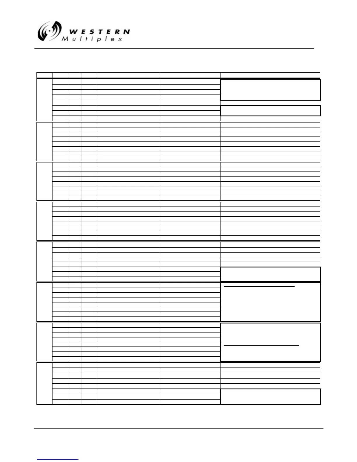
Byte Point Bit Type* Scan Point Definition Control Point Definition Notes
1 7 S Model ID MSB 0011 = 2.4 GHz E1 (Model 31500)
2 6 S Model ID LSB+2 0100 = 5.8 GHz E1 (Model 31400)
3 5 S Model ID LSB+1 0101 = 5.8 GHz 2xE1 (Model 31700)
1 4 4 S Model ID LSB 1100 = 5.8 GHz 4xE1 (Model 31850)
5 3 N/A Future Use
6 2 S Channel Plan ID MSB SW3 pos 6 00=A, 01=B, 10=C
7 1 S Channel Plan ID LSB SW3 pos 7 Defaulted to 00 (A) for Model 31800
8 0 S Channel Plan Tx High/Low SW3 pos 8 (1 = Tx High, i.e. A2, B2, C2)
9 7 A Radio Fail Alarm Equal to F/P alarm
10 6 A AIS Out Alarm Equal to F/P alarm
11 5 A Fan Alarm Equal to F/P alarm
2 12 4 A Rx Sync Alarm Equal to F/P alarm
13 3 A Loopback Error Alarm Equal to F/P alarm
14 2 A BER Alarm Equal to F/P alarm
15 1 A Far-End Alarm Equal to F/P alarm
16 0 A Telemetry Down Alarm Equal to F/P alarm
17 7 A Data Loss Ch1 Alarm Equal to F/P alarm
18 6 A Data Loss Ch2 Alarm Equal to F/P alarm, where applicable
19 5 A Data Loss Ch3 Alarm Equal to F/P alarm, where applicable
3 20 4 A Data Loss Ch4 Alarm Equal to F/P alarm, where applicable
21 3 S Data Loss Ch1 Alarm Disabled SW1 pos 1
22 2 S Data Loss Ch2 Alarm Disabled SW1 pos 2, where applicable
23 1 S Data Loss Ch3 Alarm Disabled SW3 pos 3, where applicable
24 0 S Data Loss Ch4 Alarm Disabled SW3 pos 4, where applicable
25 7 S Loopback Test Source SW1 pos 3 (0 = Internal, 1 = External)
26 6 S Loopback Error LED Mode SW1 pos 4 (0 = Latched, 1 = Momentary)
27 5 S/C Loopback Channel 1 Enabled Loopback Channel 1 On/Off Front panel switch
4 28 4 S/C Loopback Channel 2 Enabled Loopback Channel 2 On/Off Front panel switch, where applicable
29 3 S/C Loopback Channel 3 Enabled Loopback Channel 3 On/Off Front panel switch, where applicable
30 2 S/C Loopback Channel 4 Enabled Loopback Channel 4 On/Off Front panel switch, where applicable
31 1 S AIS Disabled SW1 pos 5
32 0 S Bridge Disabled (Aux Enabled) SW1 pos 8
33 7 N/A Future Use
34 6 N/A Future Use
35 5 N/A Future Use
5 36 4 N/A Future Use
37 3 S Far-End Address Invalid 1=Address>08
38 2 S Far-End Address MSB 000=01, 001=02, 010=03,
39 1 S Far-End Address LSB+1 011=04, 100=05, 101=06,
40 0 S Far-End Address LSB 110=07, 111=08
41 7 S Near-End RSL MSB
RSLVOLTAGE ≈≈ Binary Byte(integer) x 0.04 Volts
42 6 S Near-End RSL MSB-1
43 5 S Near-End RSL MSB-2 Note The 8-bit binary value (0-255) represents
6 44 4 S Near-End RSL MSB-3 RSL values between -50 dBm and threshold.
45 3 S Near-End RSL MSB-4 Radio paths with higher RSL values will read
46 2 S Near-End RSL MSB-5 approximately five (5) to ten (10) VDC on the radio’s
47 1 S Near-End RSL MSB-6 front panel test point but be limited to a maximum
48 0 S Near-End RSL MSB-7 binary reading of 255 which represents 5 VDC.
49 7 S Near-End Tx Power MSB
50 6 S Near-End Tx Power MSB-1
51 5 S Near-End Tx Power MSB-2
7 52 4 S Near-End Tx Power MSB-3 8-bit byte derives voltage or dBm
53 3 S Near-End Tx Power MSB-4
TxPWRVOLTAGE ≈≈ Binary Byte(integer) x 0.02 Volts
54 2 S Near-End Tx Power MSB-5
55 1 S Near-End Tx Power MSB-6
56 0 S Near-End Tx Power MSB-7
57 7 S Both Fans Bad Only applies if Point 11=1
58 6 S Tx Synth Unlock Only applies if Point 9=1
59 5 S Rx Synth Unlock Only applies if Point 9=1
8 60 4 S Input Line Driver Only applies if Point 9=1
61 3 S Digital Hardware Only applies if Point 9=1
62 2 N/A Future Use Key: A = Alarm
63 1 N/A Future Use S = Status
64 0 N/A Future Use C = Control
Table 3Table 3-- F: TBOSF: TBOS Map for the Lynx E1s Map for the Lynx E1s