INSTALLATION AND MAINTENANCE MANUAL
E1 FAMILY
LICENSED & SPREAD SPECTRUM RADIOS
JUNE 2001
SECTION 2: PRODUCT DESCRIPTION PAGE 2-13
2.3 Front Panel Description
2.3.12.3.1 GeneralGeneral
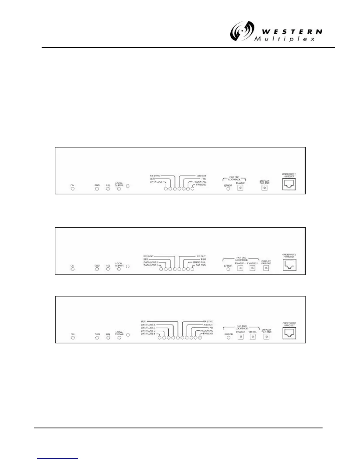
The Lynx radio front panels, as shown in Figure 2-1 through 2-6, have LED indicators, test points,
controls and connections that are used for installation, maintenance, operation and troubleshooting.
Prior to installation, it is best to be familiar with the front panel of your particular model. Sections
2.3.2 through 2.3.5 briefly describe the front panel access and lights from left to right.
Figure 2Figure 2-- 1: Front Panel, 21: Front Panel, 2.4 GHz & 5.8 GHz 1xE1.4 GHz & 5.8 GHz 1xE1
Figure 2Figure 2-- 2: Front Panel, 2.4 GHz & 5.8 GHz 2xE12: Front Panel, 2.4 GHz & 5.8 GHz 2xE1
Figure 2Figure 2-- 3: Front Panel, 2.4 GHz & 5.8 GHz GHz 4xE13: Front Panel, 2.4 GHz & 5.8 GHz GHz 4xE1