INSTALLATION AND MAINTENANCE MANUAL
LYNX E1 FAMILY
LICENSED & SPREAD SPECTRUM RADIOS
JUNE 2001
PAGE 3-58 SECTION 3: INSTALLATION & ADJUSTMENTS
3.12.4 Input Alarm (Data Loss) Enable/Disable
The Lynx radio provides a capability to enable or disable input alarms (Data Loss). On the front
panel and over the alarm and diagnostic interfaces, an alarm condition is normally generated if there
is no input data signal (E1) to the radio. For example, in the case of the double E1 capacity model,
the radio may have been installed in a location only requiring one E1 signal for traffic while the
second E1 channel has been left idle (for future planned expansion). In this case, it may be
desirable to disable the input alarm to the second channel so that local and remote alarms are not
regularly generated by the (known) lack of this data input. When the network is later expanded to
include traffic on the second E1, this switch can be set to enable the input data alarm condition.
See Figure 3-14A for DIP switch segment settings for the 4xE1 model. Refer to appendix B for all
models.
When a DATA LOSS alarm condition occurs, the Lynx radio will
inject AIS into the incoming data stream, even if the input alarm
has been disabled.
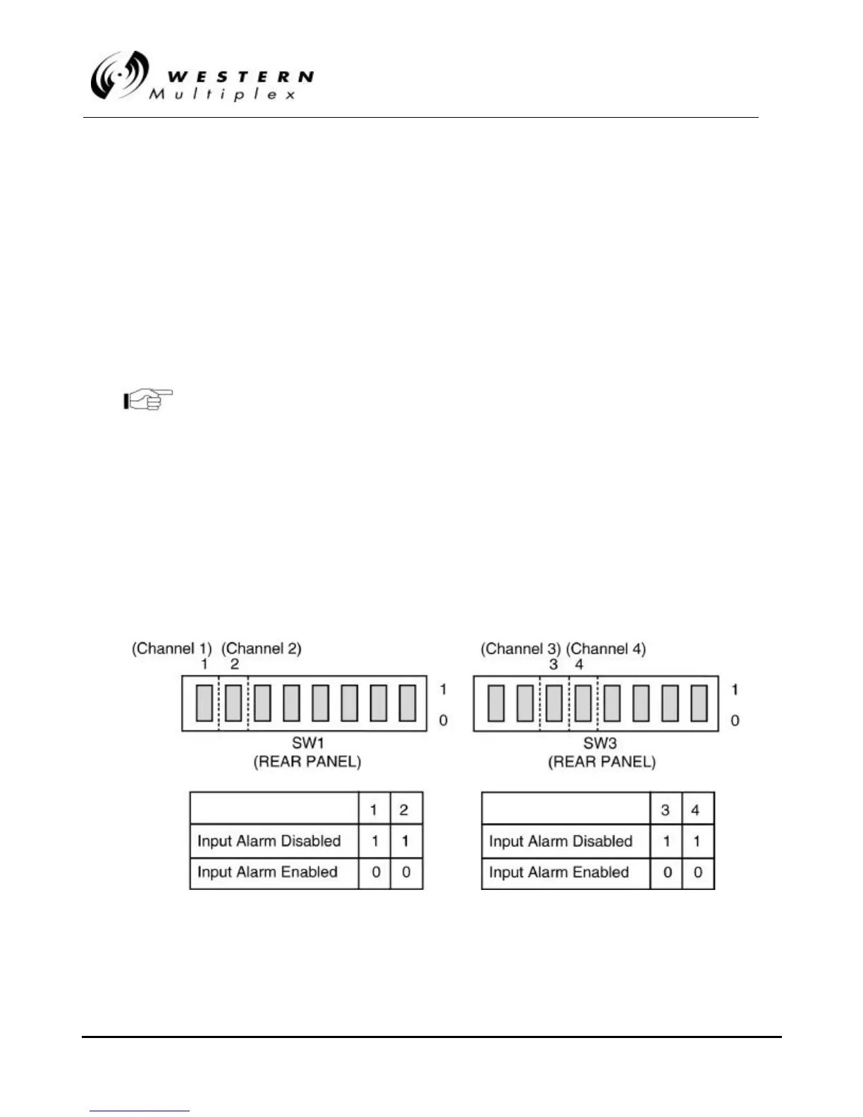
1xE1 and 2xE1 Models:
On SW1, switch segment(s) 1 (and 2) apply to channels 1 and 2 respectively.
4xE1 Models:
On SW3, switch segment 3 applies to Channel 3 input while switch segment 4 applies to Channel 4
input.
8xE1 Model:
On SW4, switch segments 1 through 8 apply to Channels 1 through 8 input, respectively.
Figure 3Figure 3-- 14A: Input Alarm Disable Switch, 1xE1, 2xE1, 4xE114A: Input Alarm Disable Switch, 1xE1, 2xE1, 4xE1