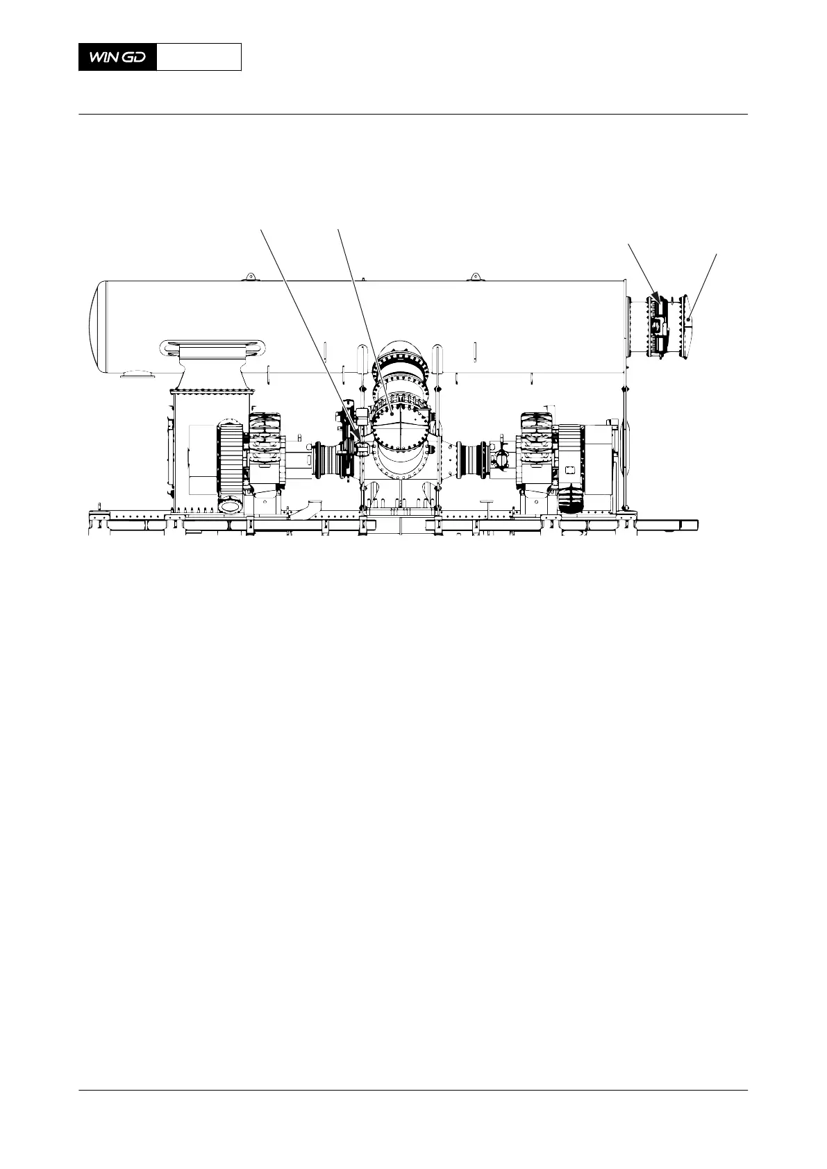
Fig 10-11 SCR system - covers (example for 2 turbocharger)
Legend
001 Cover V2 SCR outlet valve
V1 SCR inlet valve
1 Remove the cover (001, Figure 10-10 or Figure 10-11) from the flange downstream of
the valve V1.
2 Install the pipe to the SCR system to the flange.
3 Remove the cover (001) from the flange upstream of the valve V2.
4 Install the pipe to the SCR system to the flange.
CLOSE UP
• None
X35-B
AA00-9270-00AAA-520C-A
Operation Manual Connect the HP SCR system after isolation
Winterthur Gas & Diesel Ltd.
- 426 - Issue 001 2019-10