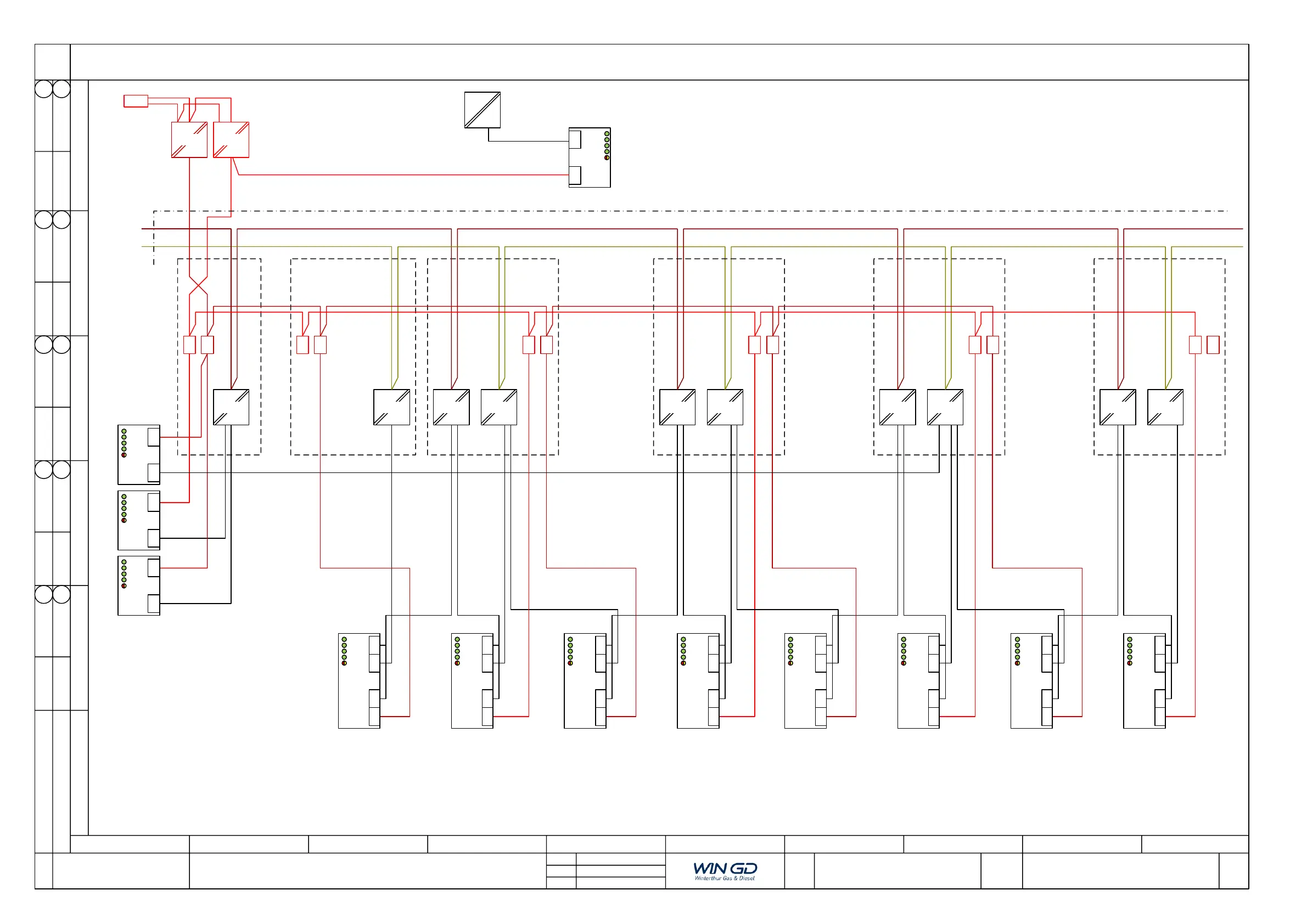
Electric Connection Diagram
System Layout
W-X35-B
W-X40-B
FEDCBA
Winterthur Gas & Diesel Ltd. retains all rights to this drawing. By taking possession of the drawing, the recipient recognizes and honors these rights. Neither the
whole nor any part of this drawing may be used in any way for construction, fabrication or marketing or any other purpose nor copied in any way nor made
accessible to third parties without the previous written consent of Winterthur Gas & Diesel Ltd. In case of violation, the recipient will be liable to damages.
Mod.
0
1 2 3 4 5 6 7 8 9
2 / 3
24VDC
AC
U2
24VDC
AC
U2
24VDC
AC
24VDC
AC
U1U2
24VDC
AC
U1
E85.3
24VDC
AC
24VDC
AC
U2U1
E85.5
24VDC
AC
E85.0
Mains #1
24VDC
AC
Batt.
24VDC
DC
24VDC
DC
U1
E85.2
+
-
To E85.1
2x4mm
2
2x4mm
2
Engine
Engine Control Room
E.g.
PULS CD5.241
Mains #2
24VDC
AC
U2
DC #1 DC #2
CCM-20
A8
PSS1
PSS2
PSD1
PSD2
X31X32X34X35
CCM-20
A7
PSS1
PSS2
PSD1
PSD2
X31X32X34X35
CCM-20
A6
PSS1
PSS2
PSD1
PSD2
X31X32X34X35
CCM-20
A5
PSS1
PSS2
PSD1
PSD2
X31X32X34X35
CCM-20
A4
PSS1
PSS2
PSD1
PSD2
X31X32X34X35
CCM-20
A3
PSS1
PSS2
PSD1
PSD2
X31X32X34X35
CCM-20
A2
PSS1
PSS2
PSD1
PSD2
X31X32X34X35
CCM-20
A1
PSS1
PSS2
PSD1
PSD2
X31X32X34X35
U1
E85.4
LDU-20
PSS1
PSS2
X22 X21
MCM-11
PSS1
PSS2
X34 X24
IOM-10
PSS1
PSS2
X21 X11
E85.6
LDU-20
X21
PSS1
PSS2
X22
24VDC
230 VAC
2x2,5mm
2