8
Accessories
7
Technical
specications
6
Errors
Troubleshooting
5
Maintenance
and care
4
Operation
Programming
3
Installation
2
Product
description
1
Important
information
General
information
Aug. Winkhaus GmbH & Co. KG · Berkeser Str. 6 · D-98617 Meiningen www.winkhaus.de
Subject to technical changes
Print-no. 504 474 4
01/2017
Installation, Operating and Maintenance
Instructions blueMatic EAV
41
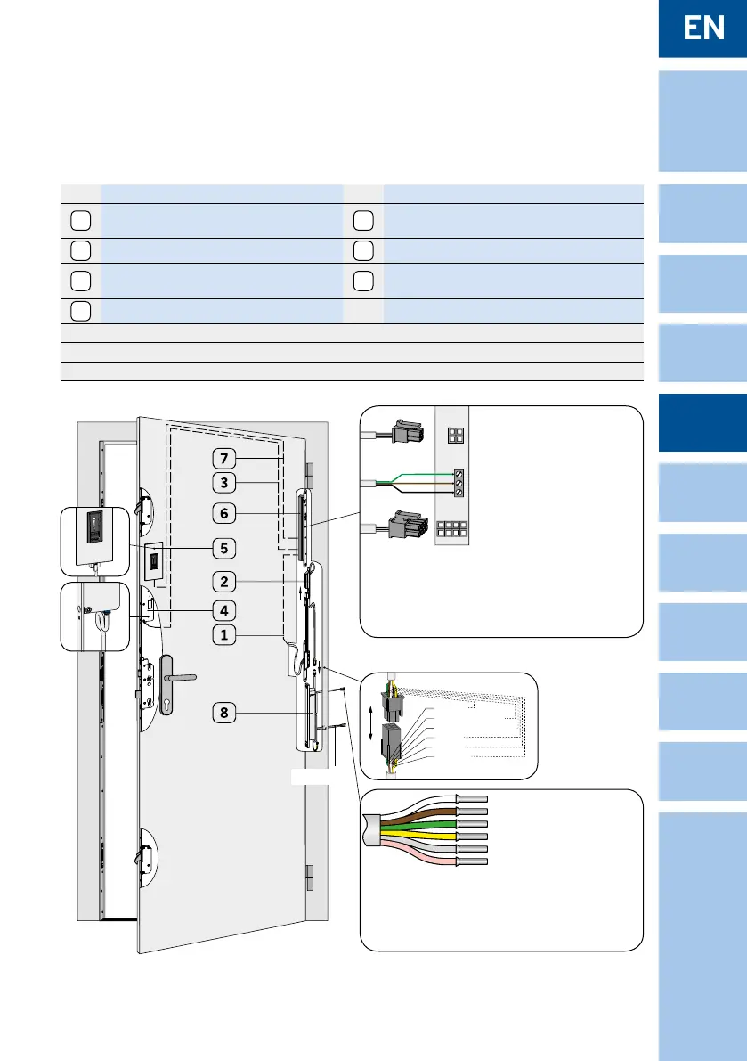
No. Description No. Description
1
Sash part seperable cable transition STV-KÜ-
T1 SET FT INTEGR-EAV FT 1M + KAB 3M
*
5
Fingerprint ekey home integra ***
2
Frame part STV-KÜ-T1 RT Kabel 4M
6
Control unit ekey home integra ***
3
Cable integra-EAV (length 3 m) *
7
Cable type „A“ ekey home integra
(length 2 m or 4 m)
***
4
Motor housing EAV **
*
at shipment Winkhaus STV-KÜ-T1 SET FT INTEGR-EAV FT 1M + KAB 3M
** at shipment Winkhaus, unmounted, for retrotting mechanical locking system
*** at shipment ekey home integra
Figure 3.6.2-2: Wiring blueMatic EAV and Fingerprint ekey home integra and frame power supply
X6
X3
X1
1
2
3
Detail B: Connections signal input frame power supply 12 V DC
Detail A: Terminal at control unit ekey home integra
Detail C:
plug-in from
frame part STV-
KÜ-T1 RT KABEL
0,6M RNT to fra
-
me power supply
12 V D
C
green
white + 12 V DC
brown 0 V DC
pink
grey
yellow
230 V AC
X1:
Connection from sash part
cable transition STV-KÜ-T1
SET FT INTEGR-EAV to the
control unit ekey home
integra with 8-pole plug
X3: Connection from control
unit to the ngerprint
(plug-in)
X6: Screw-type terminal, Con-
nection to motor housing
EAV (relay 1)
1 = white supply +
2 = brown supply -
3 = green switching pulse
green/yellow =
output relay 2 at integra 2
grey/pink = input for external potential-free
contact (e. g. unlocking via intercom/
open button)
NOTICE! max. 40 m extendable
Do not connect external voltage!
white + 12 V DC
brown 0 V
yellow
green
grey
pink
}
relay 2
(at integra 2)
}
external ope-
ning signal
 Loading...