Manual 37364A GCP-30 Packages - Genset Control
© Woodward Page 19/46
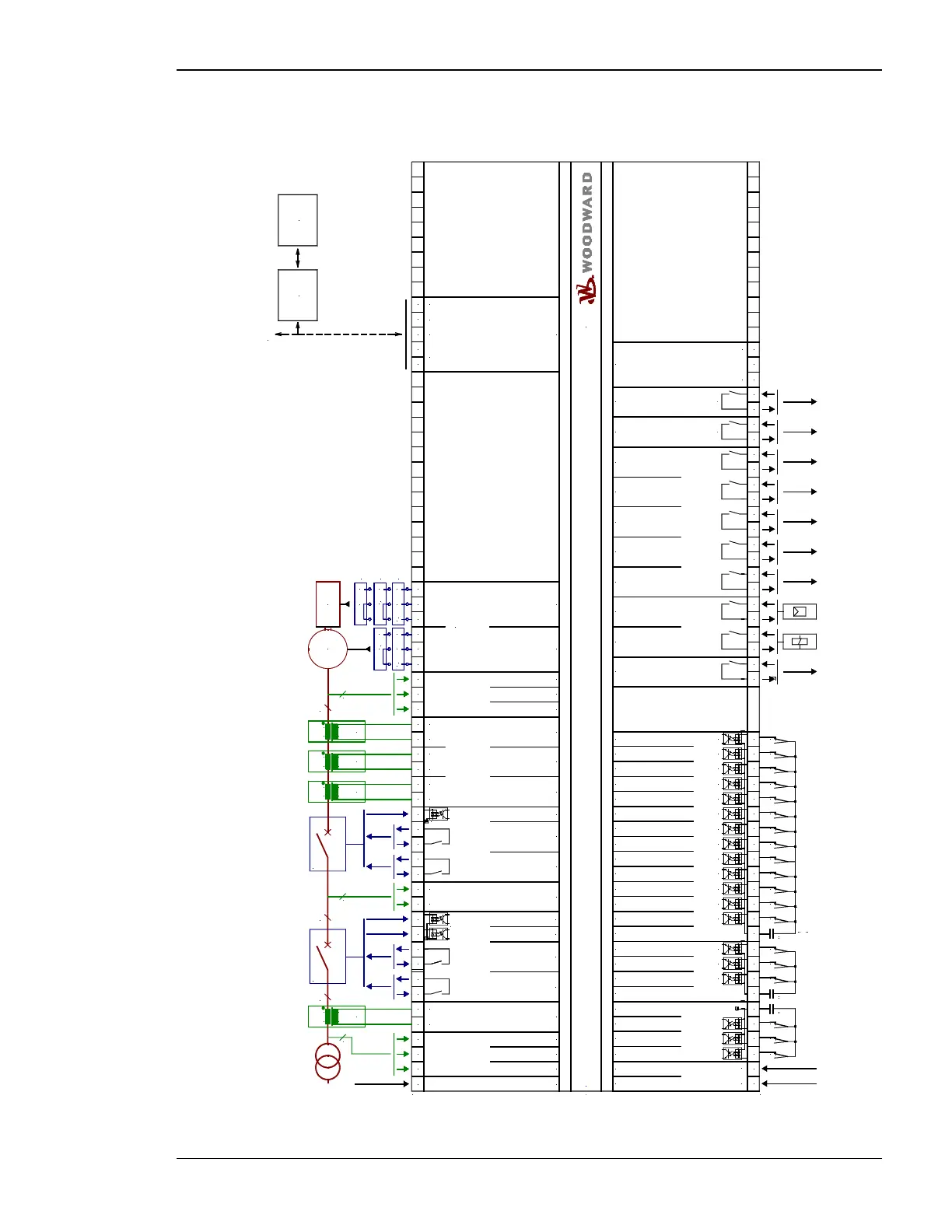
GCP-32/BPQ Package
17
Mains current L1
CAN-L
G
5
0 Vdc
2006-02-08 | GCP30 Wiring Diagram g2ww-0606-ap.skf
2
1
4
3
9
6
7
8
A
B
C
D
E
F
G
50 51 52 27 28 53 54 23 24 41 14 15 4 25 2642 29 30 31 32 20 21 22 11 12 13 8 9 10 X1 X2 X3 X4 X50
1 2 3 5 6 7 33 34 35 36 60 61 62 63 64 65 66 67 68 69 70 71 72 73 18 19 43 44 45 46 74 75 76 77 78 79 80 81 82 83 90 91 92
s2 (l)
s1 (k)
L1
L2
s2 (l)
s1 (k)
s2 (l)
s1 (k)
s2 (l)
s1 (k)
12/24 Vdc
MPU input
(Magnetic Pickup Unit)
up to 13 additional
gensets (each via
one GCP-30)
GATEWAY
GW 4
Control room
SPS
PC
Drive
Subject to technical mocifications.
Mains voltage L1
Mains voltage L3
Mains voltage L2
GCB
Reply: GCB is open
Automatic 1
Ready for operation
Automatic 2
Multi function terminal
Common (terminal 3/4/5/6/53/54)
Common
Alarm input 1
(at sprinkler: emergency stop)
Alarm input 2
Alarm input 3
Common
Alarm input 4
Alarm input 5 or
Firing speed detected by term. 62
Alarm input 6 or
Mode selection locked
Alarm input 7 or
Breaker logic
Alarm input 8
Alarm input 9
Alarm input 10 or
'GCB close' without 'eng.mon.'
Alarm input 11 or
block emergency operation
Alarm input 12
Alarm input 13 or
'Idle mode'
Alarm input 14
Alarm input 15
Alarm input 16
Start relay / Gas valve
Starter
Relay 1
Relay 2
Relay 3
Relay 4
Relay 5
Command: open GCB
Generator current L1
Generator current L2
Generator current L3
Generator voltage L1
Generator voltage L2
Generator voltage L3
Command: close GCB
The socket for the PC configuration is situated on the
side of the unit. This is where the DPC has to be plugged in.
CAN bus interface
Guidance level
GND -
switching/inductive +
GND
CAN-H
Te r mi n a t i o n
Relay 6
3837
Relay 7
4847
Standard =
Ignition / preglow
Standard =
Centralized alarm
configurable during setup (NO/NC)
#1
#1
Battery or another power supply; terminal 7/33/60 is pos. or neg. signal
#2
NO/
NC
40 1639
MCB
Reply: MCB is open
Command: close MCB
Enable MCB
Command: open MCB
Busbar voltage
Battery
#2
#2
Battery
Battery
#2
#1
NO/
NC
#1
NO/
NC
#1
NO/
NC
#1
NO/
NC
#1
NO/
NC
#1
NO/
NC
#1
NO/
NC
#1
NO/
NC
#1
NO/
NC
#1
NO/
NC
#1
NO/
NC
#1
NO/
NC
#1
NO/
NC
#1
NO/
NC
#1
NO/
NC
#1
NO/
NC
#1
NO/
NC
#1
NO/
NC
starting firmware version 4.2xxx
3/(4)
3
s1 (K) s1 (k)
s2 (L) s2 (l)
s1 (K)
s2 (L) s2 (l)
s1 (K) s1 (k)
s2 (L) s2 (l)
s1 (k)
L2
L1
L3
3/(4)3/(4)
3
s1 (K) s1 (k)
s2 (L) s2 (l)
L1
2
GCP-32/BPQ
PWM
quasi-continuous controller
with analog outputs (three-position
controller via relay manager;
ext. R/C connection!)
DC
current
DC
voltage
PWM
SPEED / POWER
(analog controller output)
VOLTAGE / POW. FAC.
(analog controller output)
GND
GND
GNDPWM
U
A
N/C
I
A
GND
U
A
GNDN/C
I
A
Common =
terminal 7
Common = terminal 7
1716
Neutral / chassis ground
+
-
Figure 4-6: Wiring diagram GCP-32/BPQ Package

 Loading...


