Manual 37364A GCP-30 Packages - Genset Control
Chapter 5.
Connectors - Details
WARNING
All technical data and ratings indicated in this chapter are not definite! Only the values indicated in
Technical Data on page 42 are valid!
The following chart may be used to convert square millimeters [mm²] to AWG and vice versa:
AWG mm² AWG mm² AWG mm² AWG mm² AWG mm² AWG mm²
30 0.05 21 0.38 14 2.5 4 25 3/0 95 600MCM 300
28 0.08 20 0.5 12 4 2 35 4/0 120 750MCM 400
26 0.14 18 0.75 10 6 1 50 300MCM 150 1000MCM 500
24 0.25 17 1.0 8 10 1/0 55 350MCM 185
22 0.34 16 1.5 6 16 2/0 70 500MCM 240
Table 5-1: Conversion chart - wire size
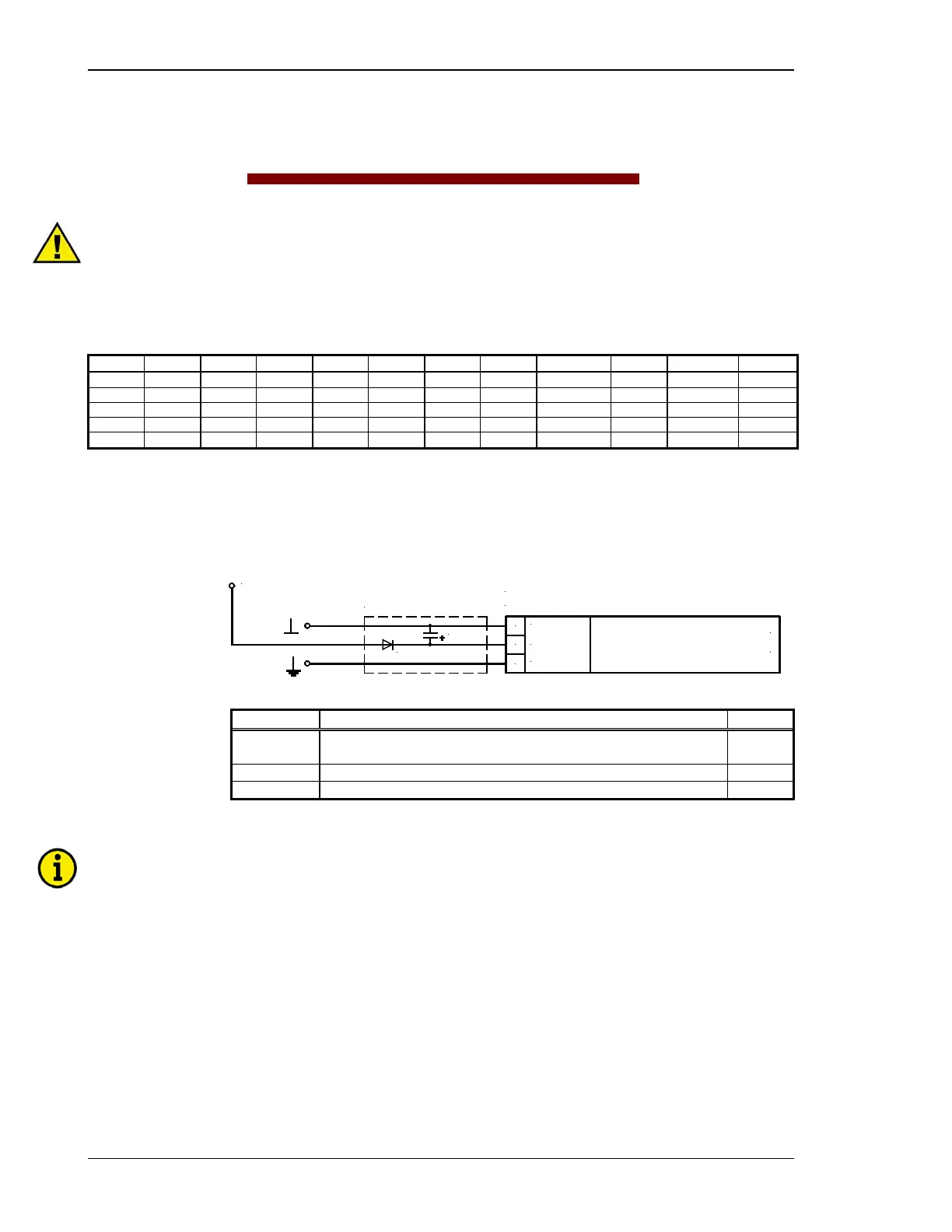
Power Supply
≡≡≡≡≡≡≡≡≡≡≡≡≡≡≡≡≡≡≡≡≡≡≡≡≡
0 1 2
N
0 Vdc
D1
C1
C1 = 47,000 uF / 40 V
D1 = P600M
for 12 V DC systems
Power supply
9.5 to 32 V DC (in normal operation)
(min. 12 V DC to start)
9.5 to 32 Vdc
9.5 to 32 Vdc
Figure 5-1: Power supply
Terminal Description A
max
0
Neutral point of the three-phase wye system or neutral terminal of the
voltage transformer (Measuring reference point)
2.5 mm²
1 9.5 to 32 Vdc, 15 W 2.5 mm²
2 0 Vdc reference point 2.5 mm²
Table 5-2: Terminal assignment - power supply
NOTE
Please note the above description in an application with 12 Vdc power supply.
Page 24/46 © Woodward

 Loading...


