Manual 37364A GCP-30 Packages - Genset Control
Measuring Inputs
≡≡≡≡≡≡≡≡≡≡≡≡≡≡≡≡≡≡≡≡≡≡≡≡≡
Voltage
Generator
L1
L2
L3
N
Generator voltage
MCB GCB
0
N
20 21 22
L3
L2
L1
G
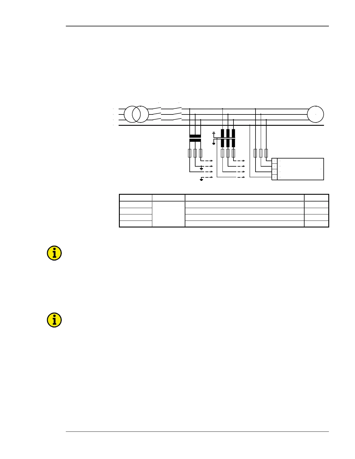
Figure 5-2: Measuring inputs - Voltage - Generator
Terminal Measurement Description A
max
20
400 Vac or
../100 Vac
Generator voltage L1 2.5 mm²
21 Generator voltage L2 2.5 mm²
22 Generator voltage L3 2.5 mm²
0 Neutral point of the 3-phase wye system/transformer 2.5 mm²
Table 5-3: Terminal assignment - generator voltage measuring
NOTE
A GCP-30 controller with 400V PT inputs and potential transformers with 100V secondary outputs must
be used for 480V delta applications. The GCP-30 will not properly protect the generator or system from
overvoltage fault conditions if a GCP-30 with 100V PT inputs is used with 100V potential transformers
or a 400V PT input unit is directly connected to a 480V system. The 100V model inputs are limited to
measuring voltage up to 125V and an overvoltage fault would exceed this range. The 400V model of the
GCP-30 is also unable to monitor for overvoltage faults if potential transformers are not utilized due to
the overvoltage fault exceeding the voltage monitoring range of maximum 500V as well.
NOTE
If a three-wire system is connected, terminal 0 must remain disconnected. If terminal 0 is connected,
the control may monitor a voltage that exceeds the permissible limits.
© Woodward Page 25/46

 Loading...


