Manual 37364A GCP-30 Packages - Genset Control
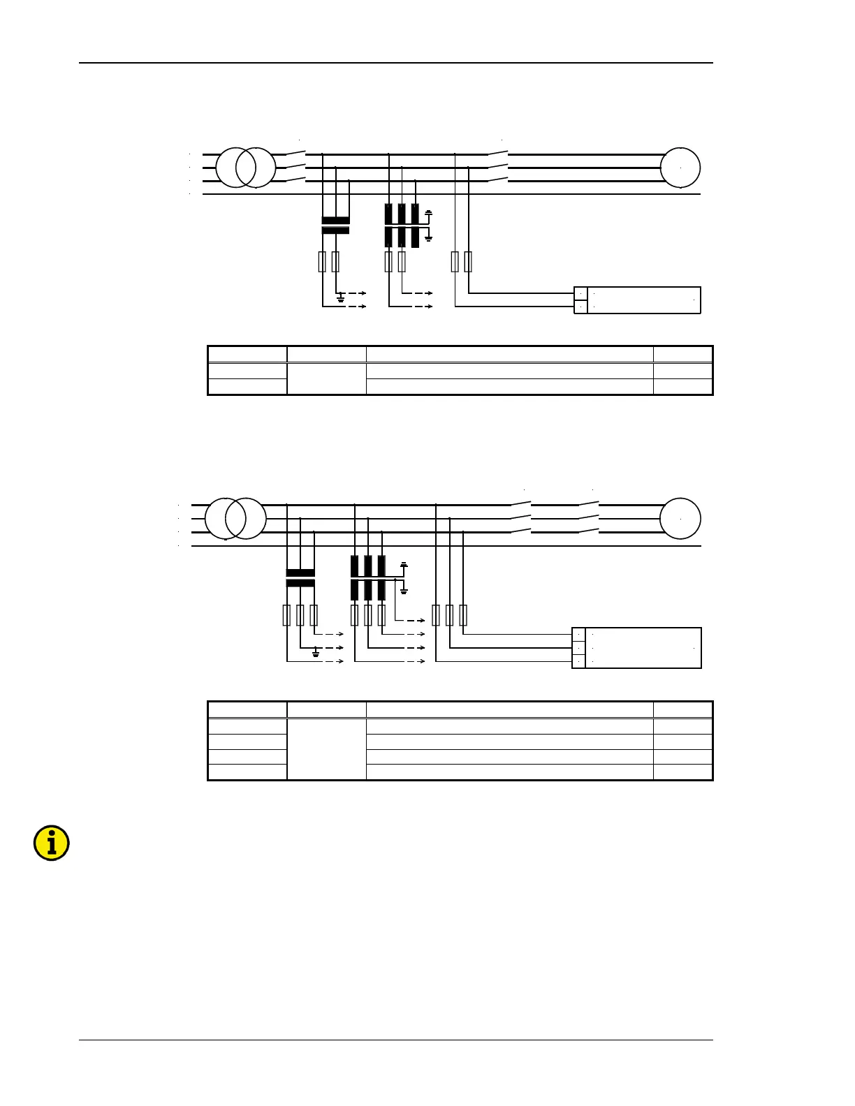
Busbar
23 24
L2
L1
MCB GCB
N
L1
L2
L3
Busbar voltage
G
Figure 5-3: Measuring inputs - Voltage - Busbar
Terminal Measurement Description A
max
23
400 Vac or
../100 Vac
Busbar voltage L1 2.5 mm²
24 Busbar voltage L2 2.5 mm²
Table 5-4: Terminal assignment - busbar voltage measuring
Mains
L3
L2
L1
N
Mains voltage
MCB
52
L3
5150
L2
L1
GCB
G
Figure 5-4: Measuring inputs - Voltage - Mains
Terminal Measurement Description A
max
50
400 Vac or
../100 Vac
Mains voltage L1 2.5 mm²
51 Mains voltage L2 2.5 mm²
52 Mains voltage L3 2.5 mm²
0 Neutral point of the 3-phase system / transformer 2.5 mm²
Table 5-5: Terminal assignment - mains voltage measuring
NOTE
The mains voltage measuring inputs must be connected if a GCP-31 is used in mains parallel opera-
tion.
Page 26/46 © Woodward

 Loading...


