Manual 37364A GCP-30 Packages - Genset Control
Page 14/46 © Woodward
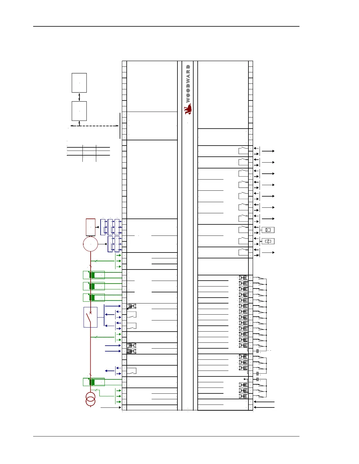
GCP-31/BPQ Package
-
+
Neutral / chassis ground
16
not connected
17
YES (e.g. 24 Vdc)YES (e.g. 24 Vdc)
Command: open external CB
(Mains decoupling)
Functional table for terminals 53/54:
See funct. table above on the left
Aim at mains parallel
operation with MCB
"EXTERNAL"
Common = terminal 7
Common =
terminal 7
A
I
N/C GND
A
U
GND
A
I
N/C
A
U
PWM GND
GND
GND
VOLTAGE / POW. FAC.
(analog controller output)
SPEED / POWER
(analog controller output)
PWM
DC
voltage
DC
current
quasi-continuous controller
with analog outputs (three-position
controller via relay manager;
ext. R/C connection!)
PWM
GCP-31/BPQ
2
L1
s2 (l)s2 (L)
s1 (k)s1 (K)
3
3/(4)
L3
L1
L2
s1 (k)
s2 (l)s2 (L)
s1 (k)s1 (K)
s2 (l)s2 (L)
s1 (K)
s2 (l)s2 (L)
s1 (k)s1 (K)
3
3/(4)
starting firmware version 4.2xxx
NO/
NC
#1
NO/
NC
#1
NO/
NC
#1
NO/
NC
#1
NO/
NC
#1
NO/
NC
#1
NO/
NC
#1
NO/
NC
#1
NO/
NC
#1
NO/
NC
#1
NO/
NC
#1
NO/
NC
#1
NO/
NC
#1
NO/
NC
#1
NO/
NC
#1
NO/
NC
#1
NO/
NC
#1
NO/
NC
#1
#2
Battery
Battery
#2
#2
Battery
Busbar voltage
39 40
YES (e.g. 24 Vdc)NO (e.g. 0 Vdc)Mains parallel operation
NO (e.g. 0 Vdc)YES (e.g. 24 Vdc)Isolated operation
Terminal 53Terminal 54Meaning
Isolated operation
NO/
NC
#2
Battery or another power supply; terminal 7/33/60 is pos. or neg. signal
#1
#1
configurable during setup (NO/NC)
Standard =
Centralized alarm
Standard =
Ignition / preglow
47 48
Relay 7
37 38
Relay 6
Termination
CAN-H
GND
switching/inductive +
GND -
CAN bus interface
Guidance level
The socket for the PC configuration is situated on the
side of the unit. This is where the DPC has to be plugged in.
Command: close GCB
Generator voltage L3
Generator voltage L2
Generator voltage L1
Generator current L3
Generator current L2
Generator current L1
Command: open GCB
Relay 5
Relay 4
Relay 3
Relay 2
Relay 1
Starter
Start relay / Gas valve
Alarm input 16
Alarm input 15
Alarm input 14
Alarm input 13 or
'Idle mode'
Alarm input 12
Alarm input 11 or
block emergency operation
Alarm input 10 or
'GCB close' without 'eng.mon.'
Alarm input 9
Alarm input 8
Alarm input 7 or
Breaker logic
Alarm input 6 or
Mode selection locked
Alarm input 5 or
Firing speed detected by term. 62
Alarm input 4
Common
Alarm input 3
Alarm input 2
Alarm input 1
(at sprinkler: emergency stop)
Common
Common (terminal 3/4/5/6/53/54)
Multi function terminal
Automatic 2
Ready for operation
Automatic 1
Reply: GCB is open
GCB
Mains voltage L2
Mains voltage L3
Mains voltage L1
Subject to technical modifications.
Drive
Control room
SPS
PC
GATEWAY
GW 4
up to 13 additional
gensets (each via
one GCP-30)
MPU input
(Magnetic Pickup Unit)
12/24 Vdc
s1 (k)
s2 (l)
s1 (k)
s2 (l)
s1 (k)
s2 (l)
L2
L1
s1 (k)
s2 (l)
92919083828180797877767574464544431918737271706968676665646362616036353433765321
0 X5X4X3X2X110981312112221203231302942 26254151441242354532827525150
G
F
E
D
C
B
A
8
7
6
9
3
4
1
2
2008-05-07 | GCP30 Wiring Diagram g2ww-0819-ap.skf
0 Vdc
5
G
CAN-L
Mains current L1
Figure 4-1: Wiring diagram GCP-31/BPQ Package

 Loading...


