Manual 37364A GCP-30 Packages - Genset Control
MPU
≡≡≡≡≡≡≡≡≡≡≡≡≡≡≡≡≡≡≡≡≡≡≡≡≡
24 V
MPU
swiching/inductive
< 1.0 V
9091
GND
92
sw./ind.
Figure 5-12: MPU
Terminal Description A
max
90
MPU
(Magnetic Pickup Unit)
switching/inductive 2.5 mm²
91 2.5 mm²
92 GND 2.5 mm²
Table 5-14: MPU - terminal assignment
Specification of the input circuit for inductive speed sensors
Ambient temperature: 25 °C
Signal shape Sinusoidal
Minimum input voltage in the range of 200 to 10,000 Hz < 0.5 V
ef
Minimum input voltage in the range of 300 to 5,000 Hz < 0.3 V
ef
Maximum input voltage in the range of 0 to 1,500 Hz 30 V
ef
Maximum input voltage in the range of 1,500 to 10,000 Hz
30 to 60 V
eff
(linear increas-
ing)
Table 5-15: MPU - input voltage
ambient temperature increases, the minimum input voltage increases at a rate of approximate-
0.3 V/°C.
Note: As the
ly
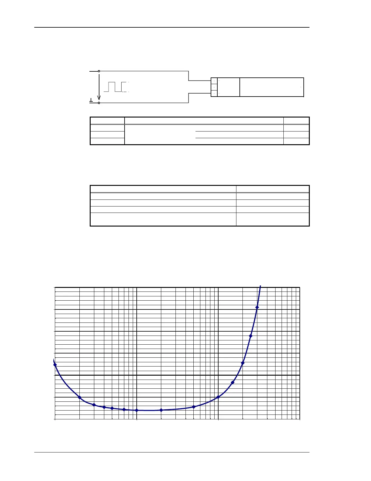
Minimum effective voltages relative to the frequency V
eff
0
0,5
1
1,5
2
2,5
3
100 1000 10000 100000
Frequency [Hz]
Minimum effective input voltage [V]
Figure 5-13: MPU - Typical behavior of the input voltage sensitivity
Page 34/46 © Woodward

 Loading...


