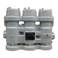
Manual 26815 QuickTrip Electro-Hydraulic Trip Block Assembly
Woodward 11
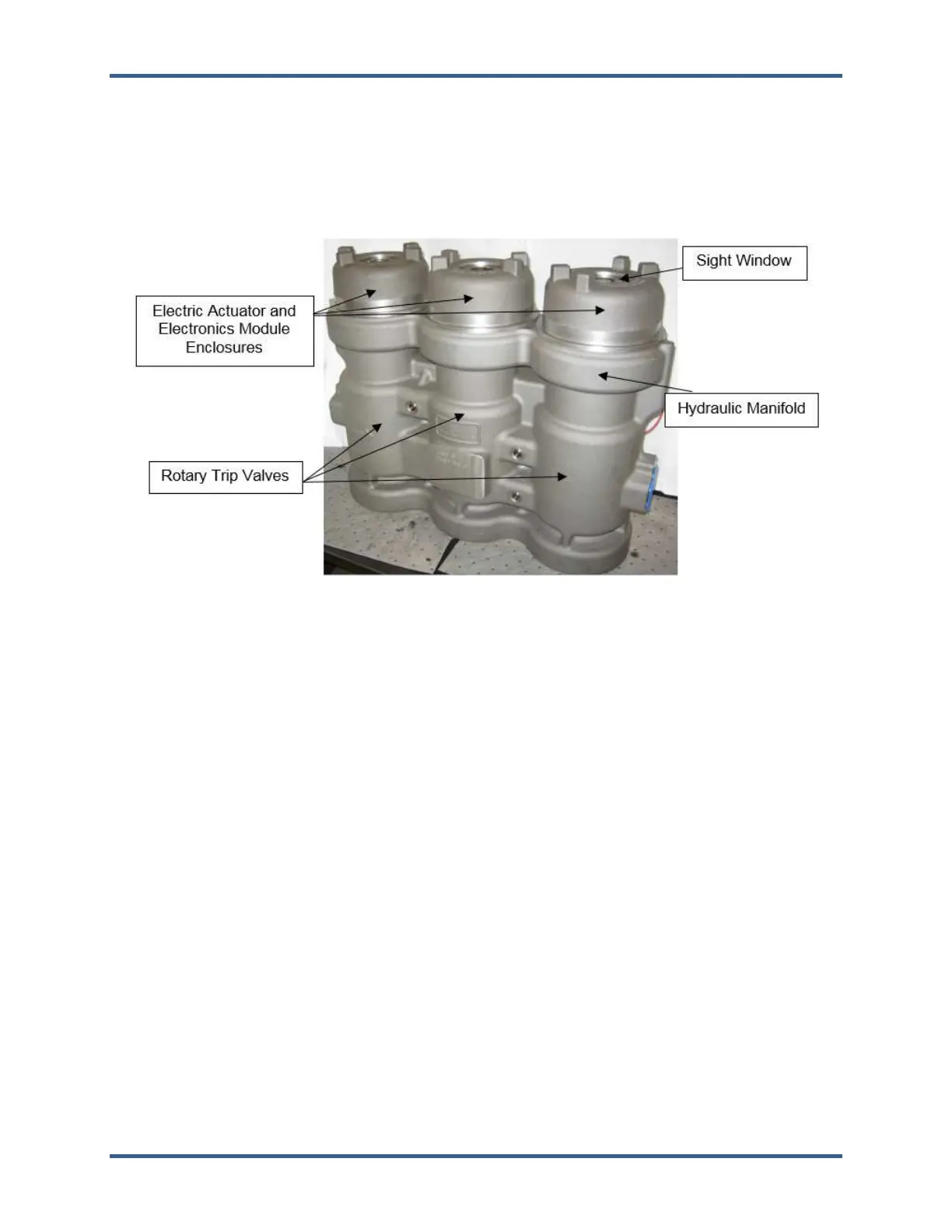
Construction
The QuickTrip is made up of the following major components:
1. Hydraulic Manifold
2. Three Independently Actuated, Spring Return Rotary Trip Valves
3. Feedback Sensors: Limit Switches
4. Integrated Electric Actuators and Electronics Modules
Figure 1-1. QuickTrip, Key Features
Rotary Trip Valves
All three of the QuickTrip’s trip valves are spring return, two position rotary valves. When any of the
hydraulic valves is in its closed position, the ports in the valve are blocked preventing hydraulic flow
through the valve. As a valve rotates to the tripped position, the ports open and the trip header pressure
is connected to either the drain, or the inlet ports of another one of the valves. The combined action of the
three valves results in trip header pressure being connected to drain only when 2 or 3 valves are tripped.
If the unit detects any shutdown condition or loss of power occurs, the trip valve return springs will force
the valves to the fail-safe / tripped position.
Electric Valve Actuators
The QuickTrip uses a set of three unique rotary solenoids called limited angle torquers (LAT). The
permanent magnet rotor is directly coupled to the trip valve.
The position of the valves is sensed by two limit switches present on each of the electrical modules.
These limit switches are located on both the closed and tripped positions of the valves, allowing the user
to easily determine the position of each valve.
Electronic Driver Modules (PCB)
The printed circuit boards (PCB) are mounted on of the top of each valve module. The PCB(s) performs
the following tasks:
• Trip Demand Input
• Dual Redundant Power Inputs
• Valve Position Feedback Discrete Outputs
• Visual Valve Position Indication