Manual 26815 QuickTrip Electro-Hydraulic Trip Block Assembly
Woodward 40
Hardware Replacement
The user is permitted to replace some components of the QuickTrip in turbine shutdown conditions. The
user is also permitted to replace some components of the QuickTrip during normal turbine operation
conditions. The replacement components must be Woodward recommended products. Only this
guarantees full component compatibility and functionality. All safety instructions and detailed procedures
from this manual must be followed.
Service and Replacement Parts:
• Service Manual (26842) – Consult Woodward distributor for part number
• Solenoid – On-line replaceable. Consult local Woodward distributor or service manual for part
number
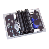
• Electronics module (PCBA) – On-line replaceable. Consult local Woodward distributor or service
manual for part number
• Return Spring – Consult local Woodward distributor or service manual for part number
• Sight Window – On-line replaceable. Consult local Woodward distributor or service manual for part
number
• Top Cover – On-Line replaceable. Consult local Woodward distributor or service manual for part
number
• Bottom Cover – Consult local Woodward distributor or service manual for part number
• Interface Seals Kit(s) – Consult local Woodward distributor or service manual for part number
• Woodward Field Repair Tools Kit – Consult Woodward distributor for part number.
Manually Stroking QuickTrip (powered)
Manually stroking valve procedure:
1. In order to manually stroke the QuickTrip valve, the actuators must be powered with 24 Vdc. Make
sure the power supply is connected and operating while performing this procedure. This can be
verified by viewing the LED status through the sight window on top of the valve. One or two blue
LED’s indicate that the power supply is connected and is turned on.
Do not remove covers or connect/disconnect
electrical connectors unless power has been switched off or the area
is known to be non-hazardous.
2. If QuickTrip is in a run state, as indicated by a green LED as viewed through the sight glass,
QuickTrip may be manually tripped either by de-energizing the logic solver interposing relay to initiate
a trip state or by tripping the breaker to the Control In discrete input terminals on the QuickTrip
electronics module (terminals 5 and 6 of TB2).
3. If QuickTrip is in a trip state, as indicated by a red as LED viewed through the sight glass, QuickTrip
may be energized to close either by activating the logic solver interposing relay to initiate a run state
or by supplying a separate
24 Vdc input to the Control In terminals on the QuickTrip electronics module (terminals 5 and 6 of
TB2).
 Loading...
