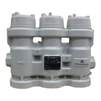
Manual 26815 QuickTrip Electro-Hydraulic Trip Block Assembly
Woodward 59
Appendix
Commissioning Checklist
When installing and commissioning the QuickTrip unit, the following checklist can be used as a guide to
ensure proper installation and successful commissioning.
Table A-1. Installation and Commissioning Checklist
Hydraulics
Trip Header and Drain
Port connections
1.250 SAE J518 Code 61
Flange
Metric Port connection
Hardware
M10 x 1.5 bolts
Torque Value
34 to 48 Nm
(25 to 35 ft-lbf)
Trip Header Pressure
34.5 bar
500 psi max
Drain Pressure
3.4
50 psi max
External Hydraulic Leaks None
Power Supply
Supply Voltage
(measured at QuickTrip
terminals)
24 Vdc ± 10%
Supply Current
(measured at QuickTrip
terminals)
2.6 Amps Max
(per module)
Wiring: PS #1 – TB1, Terminal 1
Wiring: PS #1 + TB1, terminal 2
Wiring: PS #2 - TB1, Terminal 3
Wiring: PS #2 + TB1, Terminal 4
Terminal Torque
0.2-0.25 Nm
(1.75-2.25 in-lbf)
Breakers
Breakers used between
PS + output and QuickTrip
Control Input
Wiring: Control + TB2, terminal 5
Wiring: Control - TB2, Terminal 6
Terminal Torque
0.2-0.25 Nm
(1.75-2.25 in-lbf)
Voltage 15-32 Vdc
Current 20 mA Min
Breakers
Breakers used between
Control + output and
QuickTrip
 Loading...
