Manual 26815 QuickTrip Electro-Hydraulic Trip Block Assembly
Woodward 52
Diagnostic Testing (On-Line Test)
Because of the 2-o-o-3 configuration of the QuickTrip, it is possible to perform a diagnostic test while the
QuickTrip is on-line and the turbine is running. The test procedure will set the trip outputs on the module
under test into a trip state (de-energized for a de-energize-to-trip configuration) and for only one module
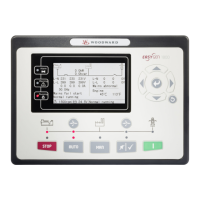
at a time. It is possible to automate the procedure shown below by using a built-in function in the ProTech
TPS called “Auto-Sequence Test” or with the programmability and test mode configurability of the
ProTechTPS, but the intent of the steps below must be met. If using a different logic solver, consult the
manual for the unit to determine the steps required to implement a diagnostic test for QuickTrip.
With the procedure below, the user can expect 83% test coverage of the dangerous failures that are not
tested by external diagnostics.
Diagnostic Test Procedure:
1. Verify that each QuickTrip module is in a run state (valve closed). This can be done by verifying that a
green light is lit on each QuickTrip electronics module, or by verifying there are no trip alarms on the
ProTech TPS (or other logic solver).
2. If using a ProTech TPS logic solver, initiate the Auto-Sequence Test by accessing the “Test Menu”,
then “Auto-Sequence Test” on the front panel (refer to Chapter 4 “Operation” for additional
information).
3. The Auto-Sequence test will automatically ramp up the internal frequency generator for module A
until it exceeds the overspeed set point at which time the control signal is interrupted and the
QuickTrip module trips. A trip alarm is momentarily displayed. Then, this module resets and the test is
repeated, sequentially, on modules B and C.
4. Once the Auto-Sequence test has completed, both ProTech TPS and QuickTrip will return to a
normally operating state.
5. Upon completion of the Auto-Sequence Test, check for any trip alarms that are not cleared and, if
ProTech is configured to do so, verify there are no run alarms (failure to energize to a run state).
6. Verify the trip time for each module by checking the Trip Cycle Time Log. This trip time can be
checked through the ProTech TPS front panel display by pressing “View Logs”, then “Trip Cycle Time
Log”. This log displays the last 20 trip events and the time from when the control signal was dropped
to the time the QuickTrip valve rotated to the open position and the trip position sensor annunciated a
trip signal back to ProTech. This trip time should be less than 50ms.
7. If there are any failures of a QuickTrip module (valve) to rotate to an open or closed state when
commanded to do so or if the trip time is greater than 50ms, consult the Repair and Troubleshooting
section in this manual (Chapter 5) for assistance.
 Loading...
