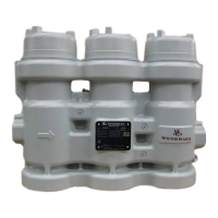
Manual 26815 QuickTrip Electro-Hydraulic Trip Block Assembly
Woodward 51
Functional Verification (Proof) Test Procedure (module level):
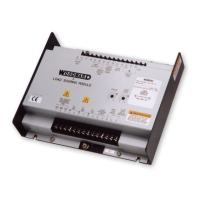
1. The following procedure should be followed for each QuickTrip module (A, B and C)
2. Ensure power is connected to one or both power inputs on QuickTrip module (terminals 1 & 2 and 3 &
4)
3. Verify that one or both blue LED’s on the QuickTrip electronics module are lit indicating that either a
single power supply or two redundant power supplies are connected and turned on.
4. Measure voltage at the QuickTrip terminals and verify that it is within the range 24 Vdc ± 10%.
5. Verify that the red LED on the QuickTrip electronics module is lit indicating the valve is in the tripped
(open) position
6. Verify trip feedback outputs are active on the QuickTrip electronics module. This can be done by
using an ohmmeter to verify continuity between terminals 7 & 8 and terminals 9 & 10 on the QuickTrip
electronics module. Note that there should be no continuity on the run feedback terminals 11 & 12
and 13 & 14. The ProTechTPS or other logic solver can also be used to detect trip feedback.
7. Use ProTechTPS or other logic solver to start the module and energize QuickTrip by applying 24 Vdc
to the control terminals (5 & 6)
8. Verify that the green LED on the QuickTrip electronics module is lit indicating the valve is in the
energized (closed) position
9. Verify run feedback outputs are active on the QuickTrip electronics module. This can be done by
using an ohmmeter to verify continuity between terminals 11 & 12 and terminals 13 & 14 on the
QuickTrip electronics module.
Note: there should be no continuity on the trip feedback terminals 7 & 8 and 9 & 10. The ProTechTPS
or other logic solver can also be used to detect run feedback if configured to do so (refer to
ProTechTPS product manuals, Woodward numbers 26501V1 and 26501V2).
10. Use ProTech or other logic solver to trip the module and verify the red LED is lit indicating the valve is
once again in the tripped (open) position
11. Using the ProTechTPS or other logic solver, check Trip Log or Trip Cycle Time Log and verify the
most recent trip time is less than 50 ms.
12. Use ProTechTPS or other logic solver to start all modules and energize all QuickTrip modules by
applying 24 Vdc to the control terminals (5 & 6) for each module.
13. Apply hydraulic pressure to the QuickTrip inlet and verify the normal operating trip header pressure is
reached.
14. Confirm the ability of the QuickTrip to hold trip header pressure when any one QuickTrip module is
tripped (module A, Module B, or Module C). Confirm this for all modules individually. Note: When any
QuickTrip module is tripped, there will be a slight decrease in trip header pressure since steady-state
hydraulic leakage through the unit increases. This slight decrease in trip header pressure should
remain above the normal trip pressure for the turbine trip system.
15. Confirm the ability of the QuickTrip to dump trip header pressure when any two QuickTrip modules
are tripped (2oo3 voting operation). Trip QuickTrip modules A and B and confirm the trip header
pressure quickly drops below the normal trip pressure for the turbine trip system.
16. Repeat the above test for the following combinations of two and three modules:
17. Modules B and C
18. Modules A and C
19. Modules A, B and C
20. If there are any failures of the QuickTrip valve to operate correctly, consult the Repair and
Troubleshooting section of this manual (Chapter 5).
 Loading...
