Manual 26815 QuickTrip Electro-Hydraulic Trip Block Assembly
Woodward 17
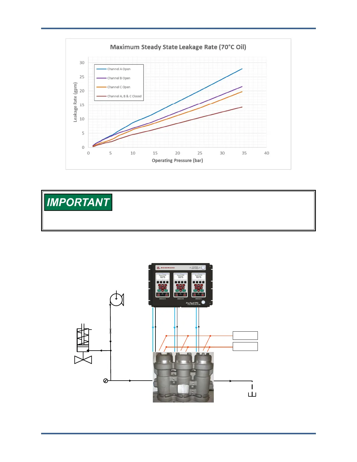
Figure 2-3. QuickTrip Steady State Leakage (70 °C hydraulic oil)
The figures above show the maximum expected steady
flow through the QuickTrip assembly during normal operation. It is
important to size the trip system orifice such that the trip header
pressure does not fall below the system trip pressure when channel A
is open (maximum leakage).
Functional Block Diagram
Trip Header
Drain
High Pressure
Supply
Supply
Orifice
Turbine Trip
Valve
QuickTrip
ProTechTPS
Trip Signal
Power Supply
24V, 9A
Redundant
Power
Supplies
Power Supply
24V, 9A
Position Feedback
Figure 2-4. Functional Block Diagram