Manual 26815 QuickTrip Electro-Hydraulic Trip Block Assembly
Woodward 31
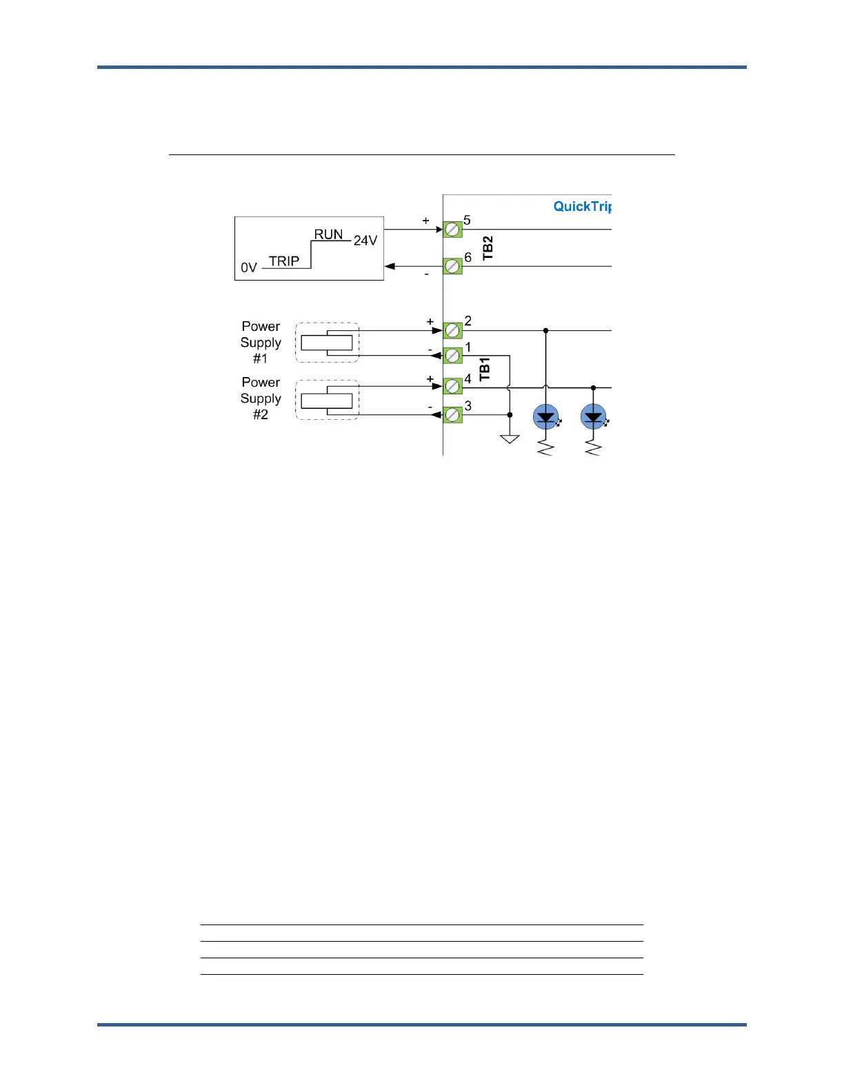
The following table presents terminal assignment for the control input.
Table 3-4. Control Input Terminals
Control In (+) Control In (-)
Control Input Terminal # 5 Terminal # 6
Figure 3-7. Control Input Connections
Wiring Requirements
• Keep this and all other low level signal cables separated from input power cables to avoid
unnecessary coupling (noise) between them.
• Wire Gauge Range: 0.8 to 1.3 mm² / 16 to 28 AWG stranded wire.
• Shielding: The Control Inputs are unshielded; however, the wires should be kept in a twisted
configuration for noise immunity.
Position Feedback
There are two outputs for valve position feedback on each of the QuickTrip’s three valve modules (12
outputs total). Each of the two outputs features redundant connections. Both TRIP outputs and both RUN
outputs operate as normally open. The outputs can be wired to either switch load from positive supply or
switch load to ground. The user must supply the external 24 V supply for the output to function properly. If
using the Woodward ProTech TPS logic solver, the voltage may be supplied using the on-board discrete
power terminals (24 Vdc, 0.050 A).
External Power Supply Voltage Range: 0-28 V
Maximum Load Current: 2 A
Response Time: Less than 10 ms
On-state Voltage drop: Less than 100 mV @500 mA
Isolation: 500 Vac from digital ground to chassis
The following table presents terminal assignment for the control input.
Table 3-5. Feedback Terminals
Trip/Run (NO) Trip/Run (Com)
Trip # 1 Out Terminal # 7 Terminal # 8
Trip # 2 Out Terminal # 9 Terminal # 10
Run # 1 Out (optional) Terminal # 11 Terminal # 12
Run # 2 Out (optional) Terminal # 13 Terminal # 14