Manual 26815 QuickTrip Electro-Hydraulic Trip Block Assembly
Woodward 36
View Alarms
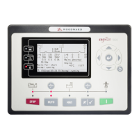
The alarm log displays a log of any alarm events that may or may not have resulted in a trip event. The
alarm log can be accessed by pressing the “VIEW” button directly underneath the “ALARM” LED indicator
on the ProTechTPS front panel. Refer to ProTechTPS manual 26501V2, Chapter 9 for additional
information.
Manually Monitoring Trip Cycle Time Log
ProTech can be configured to monitor the trip time for each QuickTrip module (see below). This trip time
can be checked through the ProTechTPS front panel display by pressing “View Logs”, then “Trip Cycle
Time Log”. This log displays the last 20 trip events and the time from when the control signal was
dropped to the time the QuickTrip valve rotated to the open position and the trip position sensor
annunciated a trip signal back to ProTech. Refer to ProTechTPS manual 26501V2, Chapters 9 and 11 for
additional information.
Configuration Options
In order to detect certain failure modes and provide diagnostic coverage for the QuickTrip, the following
configuration recommendations are provided.
1. Trip Time Monitor
Since QuickTrip is a critical part of the turbine overspeed safety system and needs to perform its
safety function quickly, it is important to continuously monitor the trip time to ensure it remains below
a certain threshold. Woodward recommends a threshold of 100 ms, but the installation site should set
this value such that the entire safety system performs is function within a safe timeframe. The Trip
Cycle Time Monitor can be accessed through the ProTech “Monitor” Menu. Refer to ProTechTPS
manual 26501V2, Chapter 9 for additional information.
2. Trip Alarm
ProTech should be configured to annunciate an alarm when any QuickTrip module annunciates a
tripped state (through the trip feedback circuit). This will provide early warning for a QuickTrip module
that fails to remain in a run state (valve fails to remain closed) when the turbine is running. Refer to
ProTechTPS manual 26501V2, Chapters 9 and 11 for additional information.
3. Run Alarm (optional)
ProTech may be configured to detect an event where the ProTechTPS module is commanded to a
run state, but QuickTrip fails to annunciate a run state (through the run feedback circuit) within a
certain timeframe (Ex. 5 sec). This configuration is optional, but may provide early warning for a
QuickTrip module that fails to energize to a run state (valve fails to close) when commanded to do so.
Refer to ProTechTPS manual 26501V2, Chapters 9 and 11 for additional information.
4. Power Failure Alarm
With input power properly applied to any QuickTrip module, that module will normally annunciate
either a run or a trip signal since the valve for that module will either be in a run or trip state. If no run
or trip signal is annunciated, then the power supplies that power QuickTrip may not be functioning.
The run and trip position switches actuate normally open relays that are operated by the same power
supplies that power the QuickTrip module. Without these power supplies, both relays and both trip
and run position annunciation outputs revert to normally open (Refer to Figure 3-2). ProTechTPS may
be configured to detect the case where one (if only one PS is used) or both power supplies fail to
provide power to any QuickTrip module. In this case, the ProTechTPS would be configured to
annunciate an alarm if both the run and the trip feedback are inactive (open) for some amount of time
(Ex. 5 seconds). Note that when the valve changes position and travels from closed to open or from
open to closed, both feedbacks will be momentarily open since the valve is in motion from one state
to another and is not actuating the trip or the run position switch during the time the valve is moving.
Also note that, if the power supplies are not functioning, the two blue LED’s on the electronics module
(PCBA) will also not be lit (see Valve Position Feedback below). Reference ProTechTPS manual
26501V2, Chapter 11 for additional information.
 Loading...
