PRE -
INSTALLATION
BOILER LOCATION &
C
LEARANCES
• This boiler is only suitable for installing
internally within a property at a suitable
location onto a fixed rigid surface of the same
size as the boiler and capable of supporting
the boiler weight.
• The boiler must be installed on a flat level
surface to ensure condensate does not enter
the primary heat exchanger.
• The boiler is not suitable for external
installation unless a suitable enclosure is
provided.
• Roof space installations must fully conform to
BS 5410 part 1 section 4.6.9.
Open flue model (CF):
• In order to ensure clean and efficient
combustion an adequate supply of air must
be delivered to the combustion chamber.
•
To provide sufficient air a suitable inlet must
be provided into the room or space in which
the boiler is situated.
An air brick or other form of continuous air
supply may have to be built into the installation
in order to ensure an adequate supply of air.
• If the appliance is to be installed in a confined
space or compartment two air vents are
required, one at high level and one at low level.
The minimum free area of each vent is
shown opposite and depends whether the
air is taken from another room or from
outside the building.
• Where the air is taken from another room that
room must contain an air inlet as described
above.
Room sealed balanced flue model (
R
S):
The appliance does not require a separate vent
for combustion air.
• Installation in cupboards or compartments
require permanent vents for cooling purposes
,
one at high level and one at low level
, either
direct to outside air or to a room.
•
B
oth vents must pass to the s
ame room or be
on the s
ame wall to the outside air.
The minimum air vent free area is given in the
table opposite.
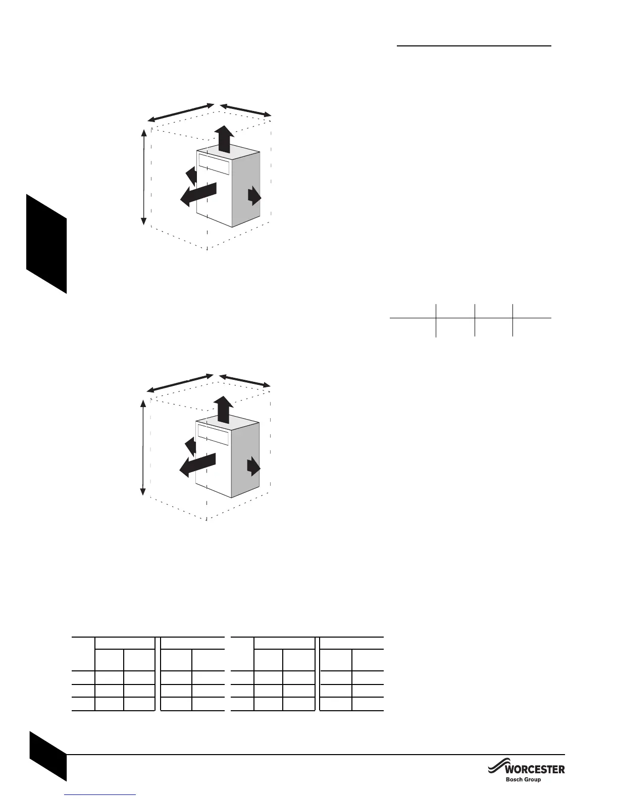
a: INSTALLATION CLEARANCES:
Diagram (
a
) shows the minimum space
recommended to inst
all the boiler only
.
b: S
E
R
VICE CLEARANCES:
Diagram (b) shows the minimum space
required to service the boiler only.
**T
he appliance is suit
able for an under
worktop inst
allation providing that the worktop
above the boiler (min 10mm clearance) is
removable for maintenance and the front of the
boiler is not enclosed.
* Remove the flue 'knock-out' panel sections if
this clearance is less than 7
5mm
.