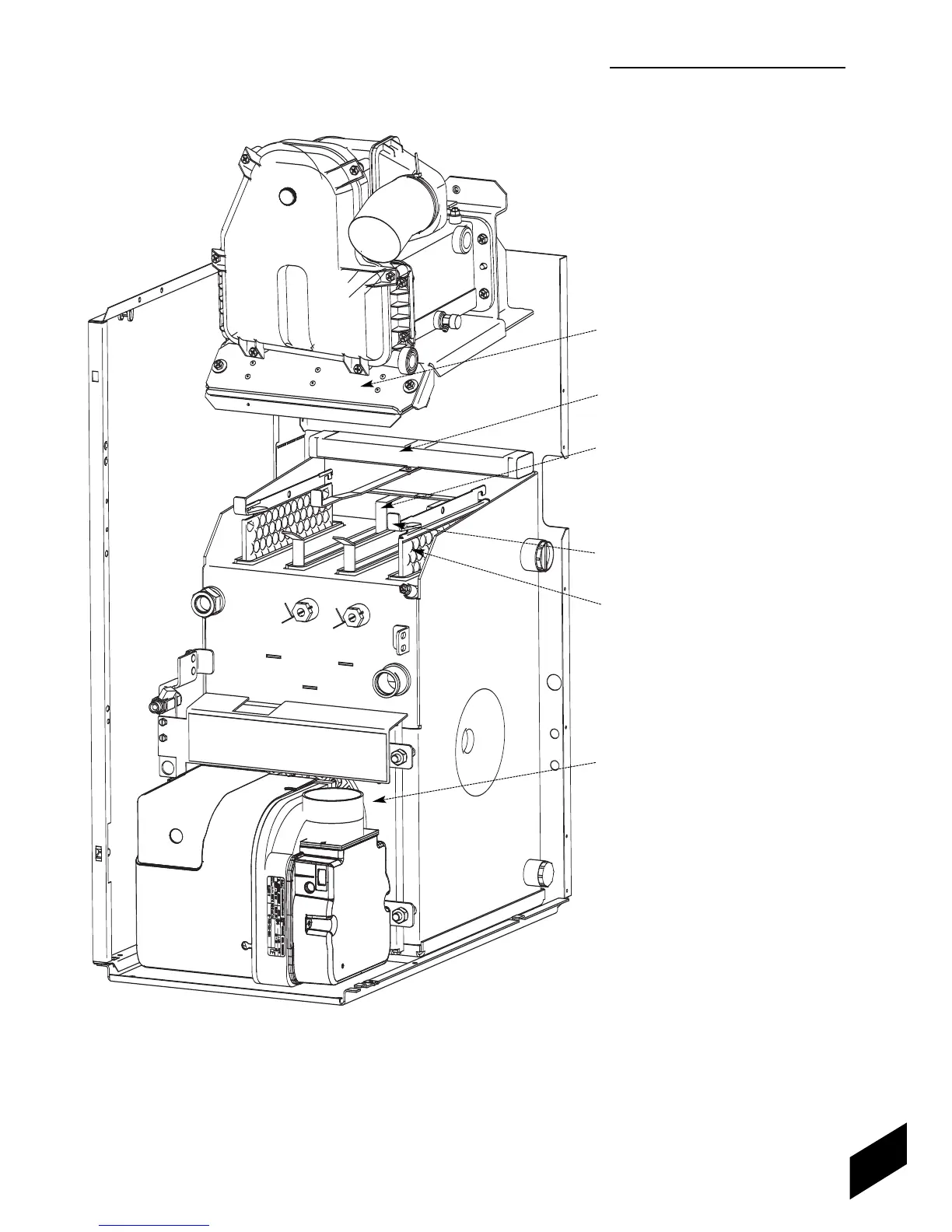
BAFFLE ARRANGEMENT
DIAGRAM
12/18 MODEL SHOWN
BAFFLE ACCESS DOOR
ACOUSTIC INSULATION INSERT
(All models)
Remove last. Refit first.
RESTRICTOR PLATE
(2 for 12/18 models, 1 for 18/25 models)
Remove and fit through baffle access door.
12/18 fitted into tubes 2 & 3.
18/25 fitted into tube 2.
BAFFLE RETAINER
Remove and fit through baffle access door.
BAFFLE
(2 for 12/18, 3 for 18/25 and 6 for 25/32)
Lift baffle to remove the baffle retainer then
pull down to remove the baffle through the
combustion chamber.
12/18 baffles in tubes 1 & 4.
18/25 baffles in tubes 1, 3 & 4.
25/32 baffles in all 6 tubes.
COMBUSTION CHAMBER ACCESS DOOR
54
1
2
3
4