INSTALLATION
COMMISSIONING
SAFETY:
All relevant safety precautions must be undertaken.
Protective clothing, footwear, gloves and safety
goggles must be worn as appropriate.
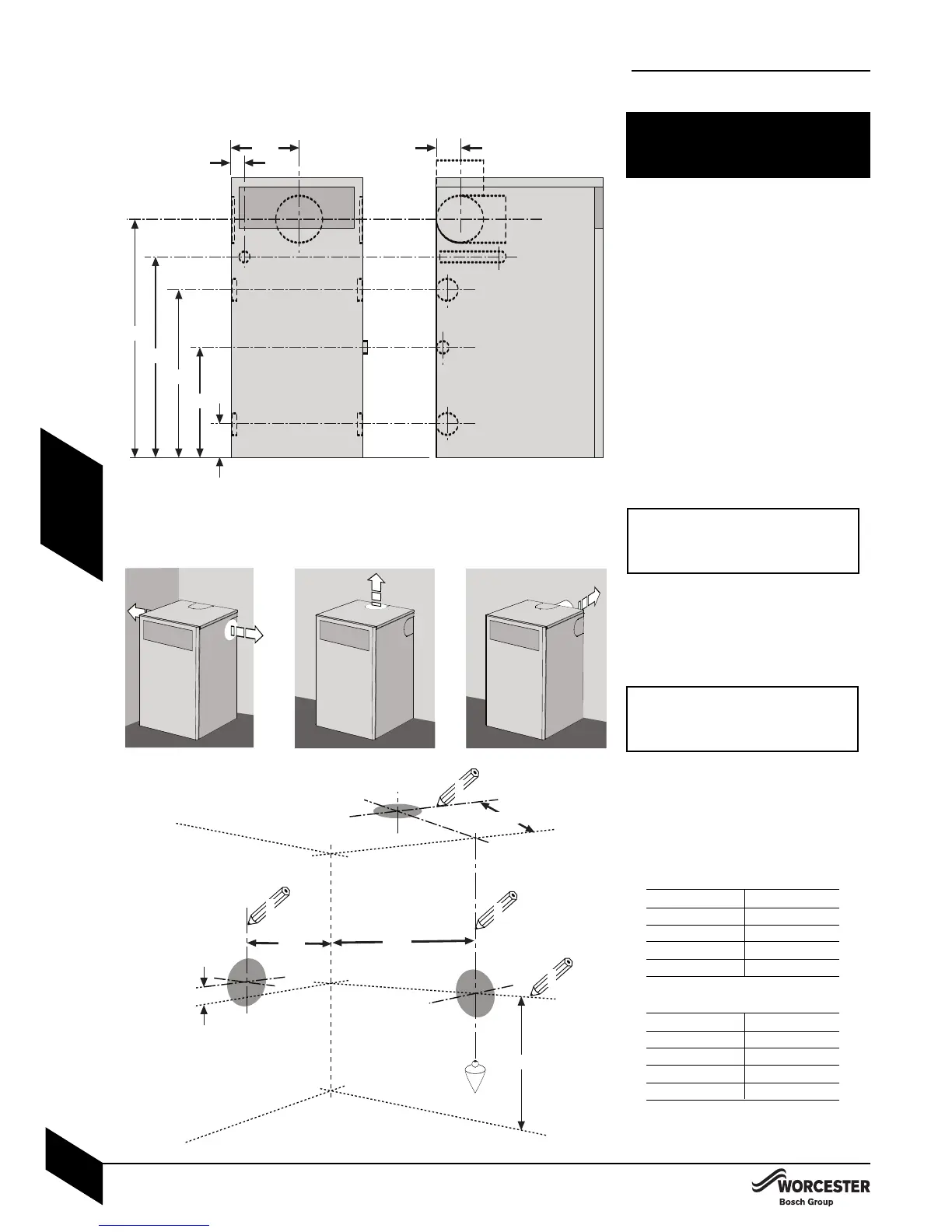
PIPEWORK POSITIONS:
A to E (opposite) show the flue and pipe positions:
A - Flow/open vent 1” BSP 12/18, 18/25.
1
1
/
4
” BSP 25/32.
B - Primary drain/cold feed
3
/
4
” Ø BSP.
C - Return 22mm Ø copper 1
2/18, 18/25.
28mm Ø copper on 25/32 model.
D - Flue outlet 80/125mm Ø.
E - Condensate outlet 21.5mm Ø.
NOTE: For servicing purposes, keep
condensate and pressure relief discharge
pipes away from components and pipework
connections.
IMPORTANT: The flue and pipework
openings are covered with tabbed blanks.
Remove carefully as necessary.
FLUE OPENING:
4 Follow the diagram opposite to mark the
centre of the flue (1, & 2) for rear opening,
(2 & 3) for side opening or
(1 & 4) for top opening.
** IMPORTANT: for horizontal flues, increase
this height by 52mm for every 1000mm of
horizontal length that the flue opening is
away from the
boiler
.
N
OTE: all horizontal flue sections must rise away
from the boiler by 52mm per metre to ensure that
condensate flo
ws back into the boiler for safe
discharge via the condensate waste pipe.
4 Make an opening (F, G or H) through the wall
using a core drill or similar at a size relative to
the wall thic
kness as shown below:
125mm Ø flue:
Wall thickness Flue hole size
150 - 240mm 155mm Ø
240 - 330mm 160mm Ø
330 - 420mm 165mm Ø
420 - 500mm 170mm Ø
150mm Ø flue:
Wall thickness Flue hole size
150 - 240mm 180mm Ø
240 - 330mm 185mm Ø
330 - 420mm 190mm Ø
420 - 500mm 195mm Ø
4 Clear away any debris.
CAUTION: Ensure there are no pipes,
electric cables, damp proof courses or
other ha
zards before drilling.
PIPEWORK POSITIONS &
FLUE OPENING
PIPEWORK POSITIONS &
FLUE OPENING
I
NSTALLATION & SERVICING INSTRUCTIONS FOR WORCESTER GREENSTAR CAMRAY KITCHEN 12/18-18/25-25/32
8 716 113 000a (01/07)
19
RS - 155
CF - 170
R
S - 155
CF - 1
7
0
1
55