INSPECTION AND SERVICE
INSTALLATION & SERVICING INSTRUCTIONS FOR WORCESTER GREENSTAR CAMRAY KITCHEN 12/18-18/25-25/32
8 7
16 113 000a (01/0
7)
43
SERVICING
& S
P
AR
E
S
INSPECTION AND SERVICE
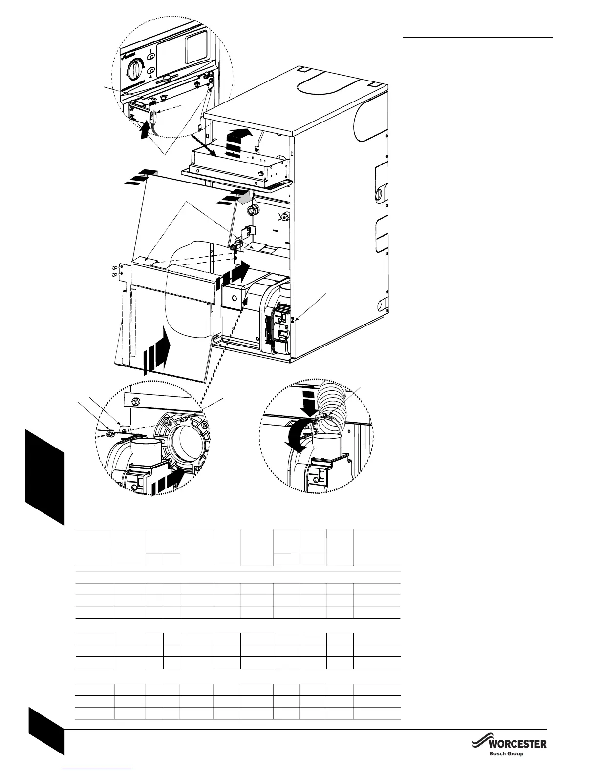
Re-commission the burner:
14 Align burner combustion head into boiler
collar.
4 Locate the burner retainer (A) over the
threaded lug on the collar (B). Push the
burner firmly onto the flange and secure in
place with the retaining nut (C). Tighten
sufficiently but refrain from overtightening.
4 Check that the burner is seated correctly
on its mounting flange and that the oil
pipe/s are not trapped in front of or
underneath the burner.
2
4 Refit the deflector plate (D) and secure
with screws (E). Ensure that the flexible oil
pipe/s are not positioned between the
deflector plate and the combustion
chamber door.
3
4 Attach air duct pipe and tighten clip (F) to
secure to the burner air intake.
44 Swing control box bac
k up into operating
position and retain in place by replacing
the two securing screws (G) in the bottom
locations
.
4 Plug burner lead (H) into control box.
4 Run the burner and check the combustion
settings as indicated in the table below
and check that the smoke reading is
between 0 - 1.
54 Locate the top edge of panel ( I ) onto the
supporting ledge ( J ) and secure at the
bottom by gently pushing home the ball
studs into the retaining slots ( K ).
Remember always to apply pressure at the
edges of the panels to avoid damage.
Aft
er service handover:
4Make a note of the date of any water treatment.
4Set the controls back to the users
requirements.
4Complete the service interval record at the
bac
k of this manual and the CD1
1 or an
equivalent form
.
4If the appliance is unused and exposed to
freezing conditions; shut off all the mains
supplies, isolate the boiler and drain the
system and boiler, including the secondary
heat exchanger.
* 25/32 model for 25kW remove the plastic
air guide (see page 36).