P
I
P
EW
O
R
K C
O
N
N
ETIONS
INSTALLATION & SERVICING INSTRUCTIONS FOR WORCESTER GREENSTAR CAMRAY KITCHEN 12/18-18/25-25/32
8 716 113 000a (01/07)
23
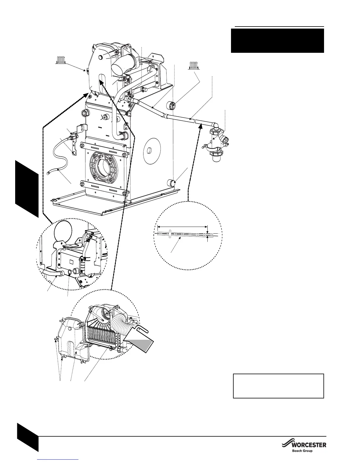
INSTALLATION
PIPEWORK CONNECTIONS
CAUTION: ISOLATE THE OIL & WATER
MAINS SUPPLY BEFORE STARTING ANY
WORK AND OBSERVE ALL RELEVANT
SAFETY PRECAUTIONS.
A - Flow/open vent 1” BSP on 12/18,
18/25 (1
1
/
4
” BSP on 25/32 models)
B - Primary drain/feed
3
/
4
” BSP
C - Return 22mm Ø copper (28mm Ø on
25/32 models)
D - Fixing point for optional return oil pipe.
E
- Oil isolating valve (10mmØ)
F - Flexible oil pipe
G - Flue manifold condensate outlet
H - Condensate outlet (21.5mmØ) -
supplied
I - Condensate pipe - not supplied
J - Condensate trap with wall clamp - supplied
WATER CONNECTIONS:
4Remove the transit bungs from the pipework
connections on the boiler.
NOTE: Surplus water may be present due to
factory testing
.
4Ensure all pipework is clean.
4Fit the return pipe (C) to the secondary heat
exchanger using the sealing washer supplied.
4Align water pipework and connect.
4Check that all unused sockets have been capped.
OIL SUPPLY CONNECTIONS:
4Route the oil supply pipe along the left
side of the boiler and connect to the isolating
valve (E) and ensure the valve is closed.
4Connect the flexible oil pipe (F) to the isolating
valve (E).
CONDENSATE CONNECTION:
4Fit the elbow (supplied) onto the
condensate pipe (H) (supplied).
4Fit the sealing washer to the condensate
pipe (H) and connect it to the flue manifold
outlet (G).
4Fit the condensate trap in a serviceable
position using the clamp supplied.
4C
onnect 21.5mm polypropylene pipe ( I ) (not
supplied) to the condensate pipe (H) and
condensate trap (J) before terminating to
waste.
4Ensure that the condensate pipe runs away
from the boiler at a constant fall of 50mm
(min.) for every metre.
4Carefully pour 500ml of water into the
condens
at
e collect
ion (
K
) t
o fill condens
ate
trap.
4Check the water is running away and the
condensate pipework joints are water tight.
4Check the flue manifold seal is undamaged
and seated correctly.
4Refit flue manifold access cover (
M
) and
secure with screws (L).
IMPORTANT: The condensate trap must be
correct
ly filled t
o prevent the possibility of
potentially harmful flue products escaping
via the condensate pipework.
A
B
C
located at the side
of the secondary
heat exchanger
H
J
G
I
D
I
E
F
Return pipe
(C)
W
asher
K
M
L