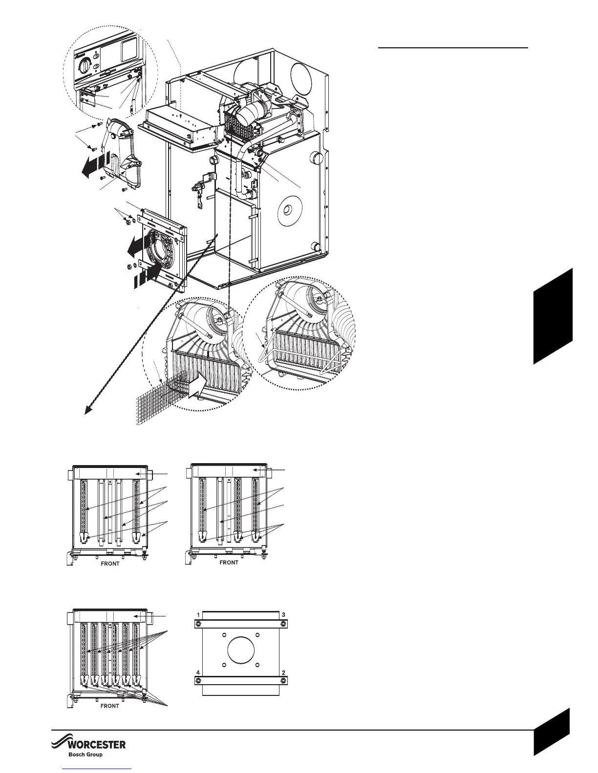
Combustion chamber:
14 Remove the control box securing screws
(A, bottom screw both sides) and loosen
the pivot screws (B, top screw both sides).
24 Pivot down control box.
34 Release retaining nuts and washers (C).
4 Remove combustion chamber access door (D).
44 Release screws (E) on either side and
remove upper access door (F).
54 Ensure baffles (G) and baffle retainers (H),
restrictor plates ( I ) and acoustic insulation
insert ( J ) are correctly fitted for the boiler
model as shown in the plan view opposite.
4Refit the upper access door (F ) and
secure with screws (E).
64 Secure combustion chamber access door
with nuts and washers (C). Tighten until
door is firmly secured using the sequence
below. Do not overtighten the nuts.
74 Unscrew screws (K) and remove flue
manifold access cover (L).
84 Chec
k that all the baffles (M) and baffle
retainer (N) are correctly fitted to the
secondary heat exchanger.
C
O
MBUSTION CHAMBER
I
N
S
TALLATION & SERVICING INSTRUCTIONS FOR WORCESTER GREENSTAR CAMRAY KITCHEN 12/18-18/25-25/32
8 716 113 000a (01/07)
22
INSTALLATION
COMBUSTION CHAMBER