CAUTION: ISOLATE THE OIL & WATER
MAINS SUPPLY BEFORE STARTING ANY
WORK AND OBSERVE ALL RELEVANT
SAFETY PRECAUTIONS.
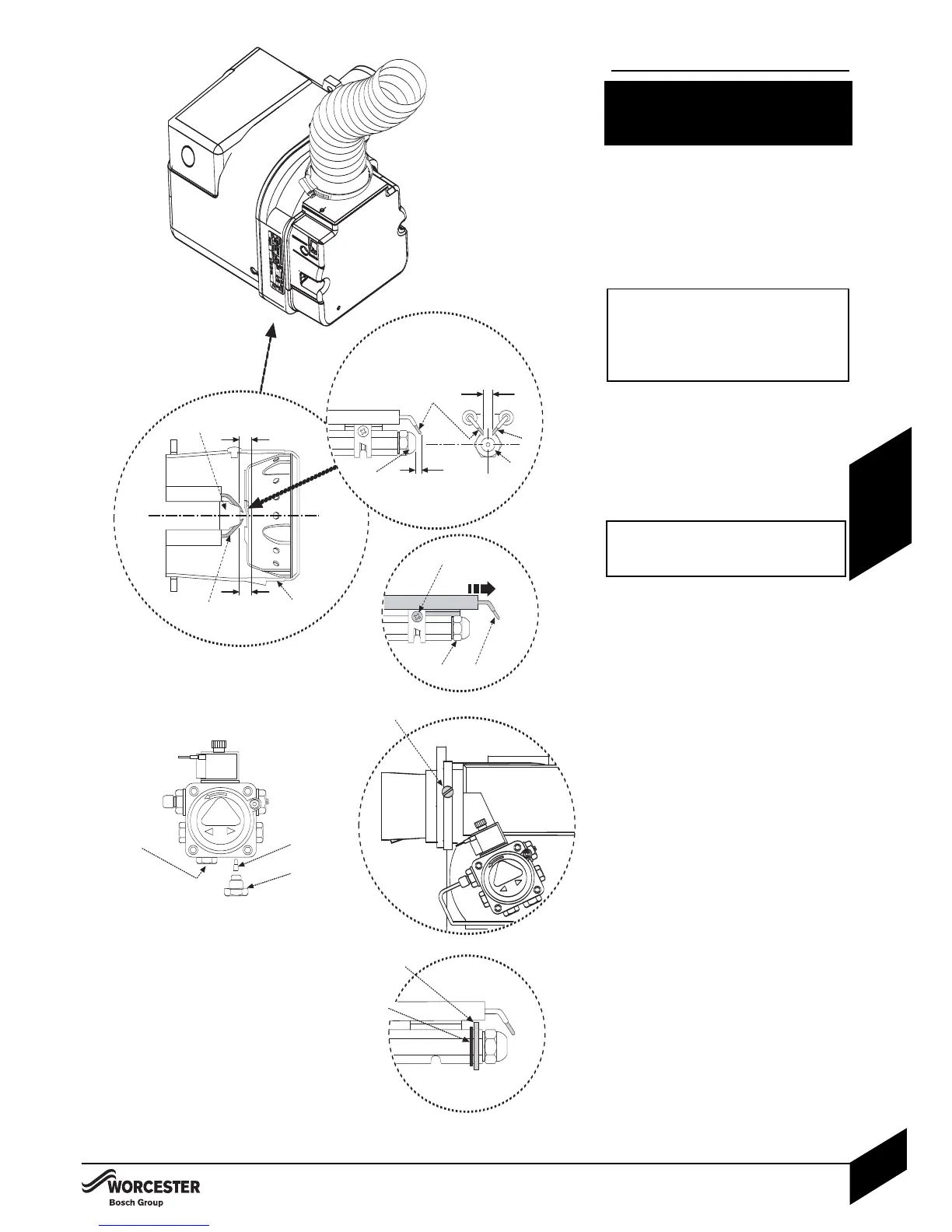
OIL BURNER:
14 Check the nozzle (A) and electrode (B)
settings are correct as shown opposite.
4 Ensure nozzle (A) is aligned centrally within
the combustion head (C).
4 Inspect for any visible defects.
2 IMPORTANT: Before removing or fitting a
nozzle (A), loosen screw (D) and move
the electrodes (B) forward.
Aft
er refitting check that the electrode
gaps are correct, as shown opposite.
NOTE: the 12/18 model has a brass deflection
washer and locating circlip behind the nozzel.
These must be in place for the correct
operation of the burner.
IMPORTANT: Whenever replacing the
combustion head, ensure that the
photocell is lined up with the sight hole.
OIL PUMP:
Connecting the oil pump for a single pipe
system:
4 The pump is factory set for single pipe
operation with the flexible oil pipe fitted.
4 Chec
k connections before use.
Converting the oil pump for a double pipe
system:
14 Check the inlet pipe connection (1).
4 Unscrew return plug (2).
4 Screw in by-pass screw (3).
24 C
onnect the flex
ible oil pipe
ret
urn
hose
(not supplied) to the oil pump and return
pipe fixing (D on page 23) and tighten
to secure.