DANGER - 230V:
ISOLATE THE MAINS ELECTRICITY
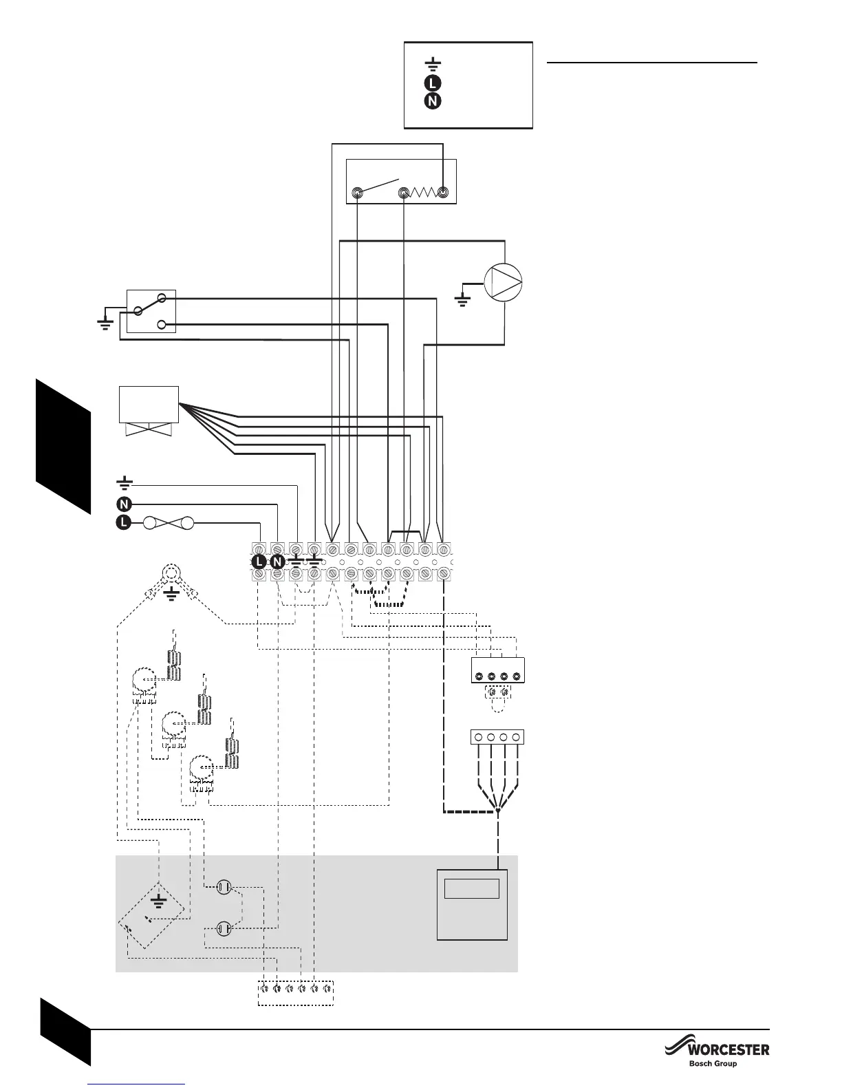
3 PORT VALVE CONTROL SET:
Key to components:
R - ROOM THERMOSTAT.
S - CIRCULATING PUMP.
F - INTERNAL PROGRAMMER CONNECTOR.
G-TERMINAL CONNECTOR BLOCK.
H - LINK CONNECTOR.
T - HOT WATER CYLINDER THERMOSTAT.
V - MID-POSITION VALVE.
P - OPTIONAL 230V WORCESTER
PROGRAMMER (fitted into fascia panel).
Terminator connector block (G):
4Remove link 1 to 3.
4Remove link 2 to 4.
4Make link 3 to 5.
Optional 230V Worcester (P):
4Set the pin on the rear of the programmer to
‘pumped’.
4Remove the link plug (H).
4Connect the plug from programmer (P) into
connector (F).
4Move the orange wire from terminal 9 to
terminal 6.